9
ASSEMBLY INFORMATION
EN 110
9 ASSEMBLY INFORMATION
9.1 Information on engine configuration
• In this chapter, the engine is represented as "BASE CONFIGURATION" (refer to Par 1.3 - Par.
1.4).
• For the assembly of components not described in this chapter refer to Chap. 11.
• The following are the components described in Chap. 11.
11.1 Oil dipstick in cylinder head
11.2 Heater (replacement)
11.3 Idler gear (for 3
rd
/ 4
th
PTO)
11.4 3
rd
PTO (replacement)
11.
5 4
th
PTO (replacement)
11.
6 3
rd
+ 4
th
PTO (configurations)
11.
7 Balancer shafts (replacement)
11.
8 Air filter (cartridge replacement)
11.
9 Remote oil filter (disassembly and assembly)
11.10 Intake circuit (replacement)
11.11 Muffler (replacement)
11.12 Cooling circuit (replacement)
11.13 Engine feet (information)
9.2 Assembly recommendations
• The information is laid out in sequence, the intervention methods have been selected, tested and
approved by the manufacturer's technicians.
• This chapter describes the installation procedures for the assemblies and/ or individual components
which have already been checked, overhauled or possibly replaced with original spare parts.
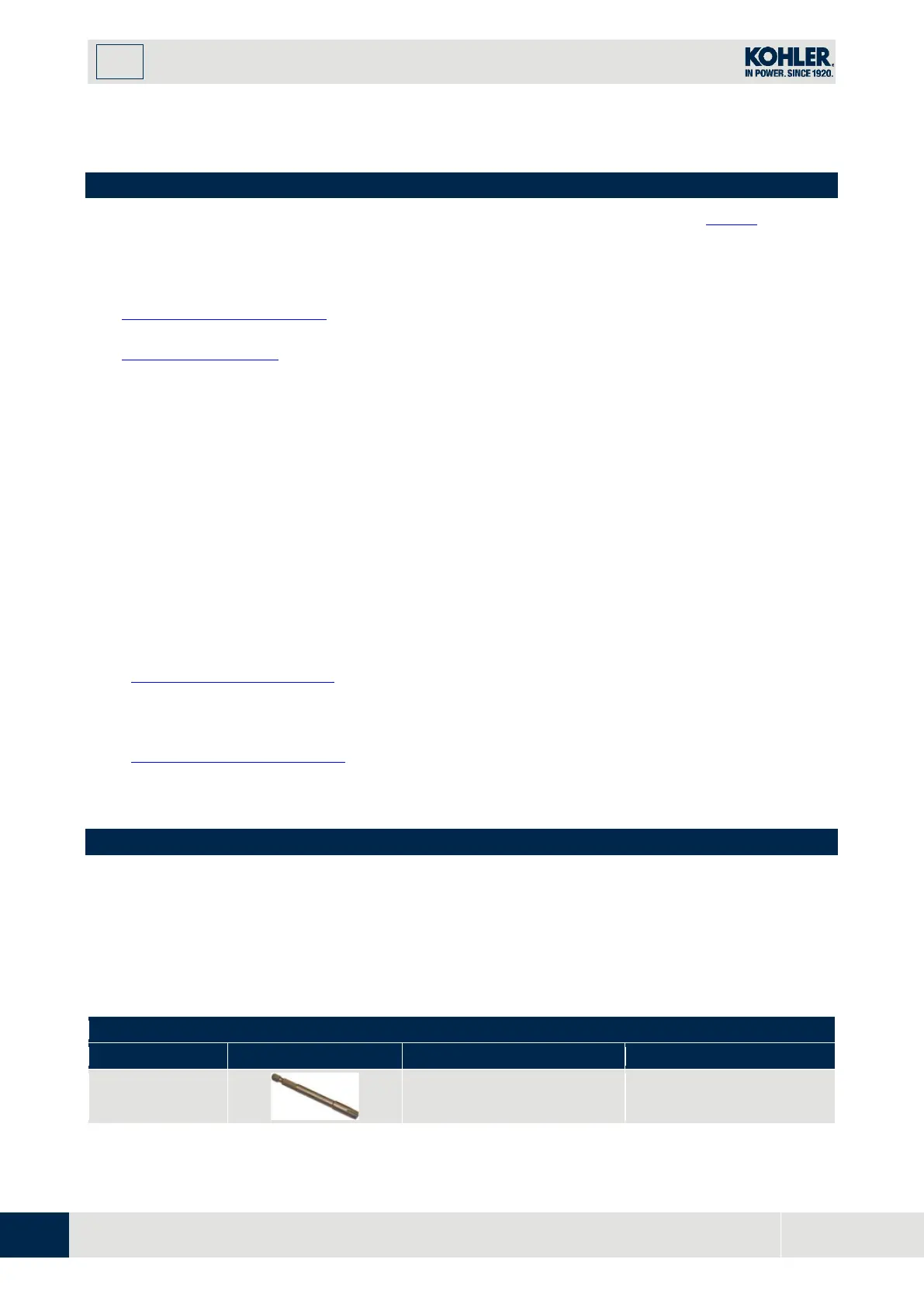
• Where necessary, reference to special tools during assembly operations is indicated and identified
in Tab. 13.1, hereinafter in Tab. 9.1 an example of a special tool (ST_05)
.
Tab. 9.1
ST_05
Six nicks Key SN 8
ED0014603650-S

 Loading...


