9
ASSEMBLY INFORMATION
EN 122
7.
Fix pump Z into housing V by means of screws T
(Fig. 9.34 - tightening torque at 25 Nm).
8.
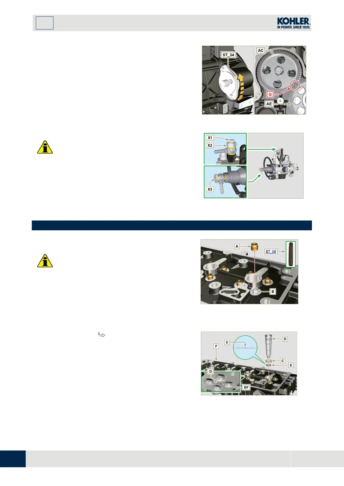
Position the gear AC onto shaft AB of the pump.
NOTE:
You are not required to respect the reference
Q
gear
AE
(
Fig.
9.36
).
9.
Insert washer U and tighten nut AD (tightening
torque at 70 Nm).
I
mportant
•
In the event of assembling screw X1 (tightening
torque at 10 Nm).
•
In the event of assembling screws X2 and X3
(tightening torque at 2 5 Nm).
Fig 9.36
Fig 9.37
9.7 Cylinder head unit assembly
Important
•
Carry out the checks described in Par. 8.6.4 befor
e
p
roceeding with the following operations.
•
Always replace gasket A with every assembly
•
Lubricate the gaskets A on the inside.
1.
Fit the oil seals A on the valve guides B using the
tool ST_08.
Fig 9.38
9.7.2 Injector sleeves
( )
1.
Insert the seals C in the seats of the sleeve D.
2.
Insert the seal E with the convex side facing
upward at the base of the sleeve D.
3.
Lubricate the gaskets C.
4.
Insert and carefully screw the sleeve D into the
seat of the head F.
NOTE: The sleeve D must not protrude above the surface
of the head BF.
5.
Clamp the sleeve D (tightening torque at 30 Nm).
Fig 9.39

 Loading...


