ASSEMBLY INFORMATION
9
119
EN
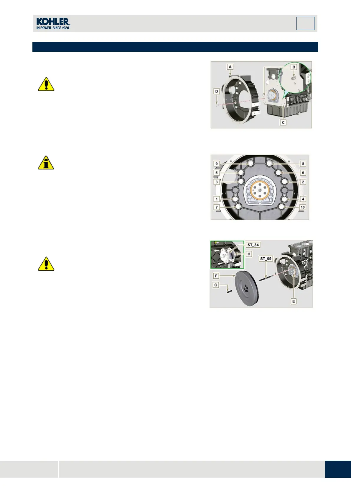
9.5 Flange unit assembly
Danger
•
Bell A is very heavy; pay special attention during
assembly operations to avoid dropping and causin
g
serious risks to the operator.
1.
Install the bell housing A in accordance with th
e
r
eference pins B on the base C.
Fig 9.27
•
Failure to adhere to the assembly procedures may
compromise the functionality of the engine, and also
cause damage to persons and property.
2.
Tighten the fastening screws D strictly following the
tightening sequence indicated (tightening torque 50
Nm).
Fig 9.28
Danger
•
Flywheel F is very heavy; pay special attention during
assembly operations to avoid dropping and causing
s
erious risks to the operator.
1.
Screw the special tool ST_09 on the crankshaft E
instead of the screws G positioned higherup (Fig.
9.29).
2.
Insert the flywheel F on the crankshaft E using the
tool as a guide ST_09 and manually tighten all the
screws G (the last screw is fitted in the place of the
tool ST_09).
3.
Mount the tool ST_34 in the seat of the starter motor
H and fit it with the two starter motor fixing screws.
4.
Tighten the screws G (tightening torque at 140 Nm)
.
Fig 9.29

 Loading...


