11
INFORMATION ABOUT OPTIONAL
COMPONENTS
EN 170
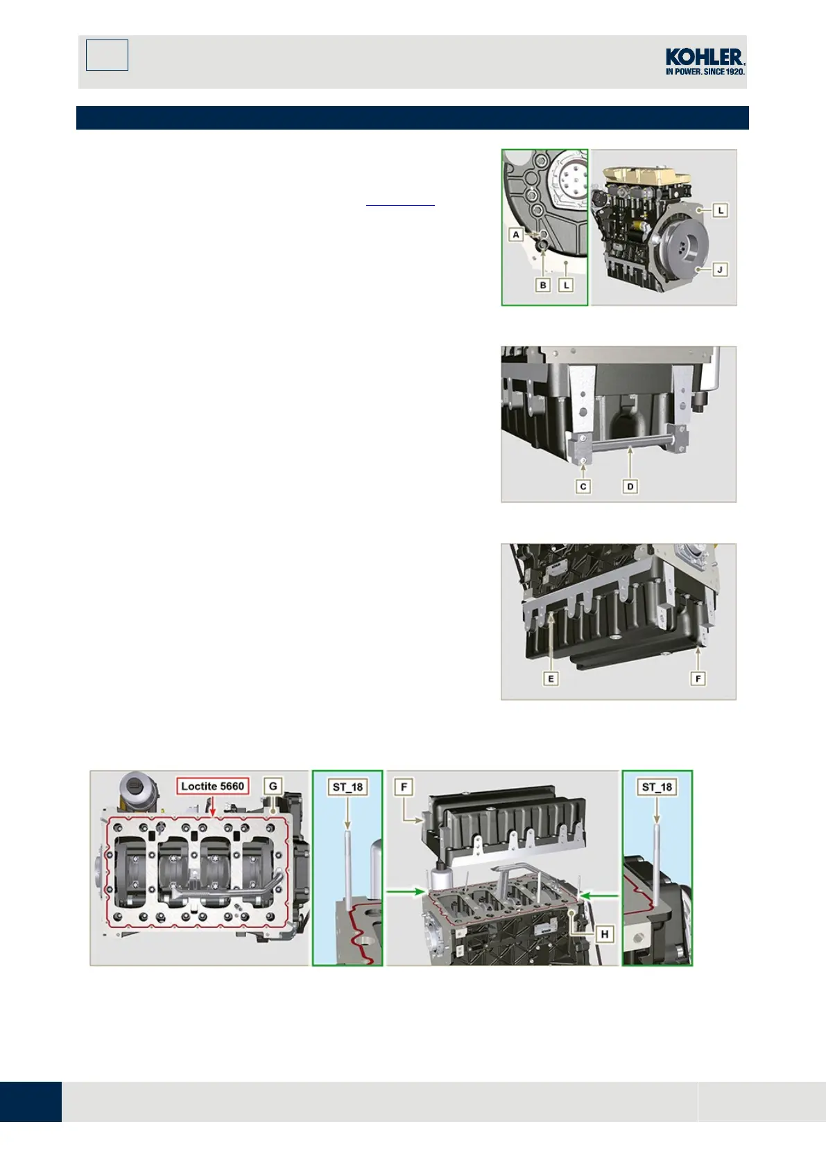
11.16 Oil sump with supporting structure
11.16.1 Flywheel (J) disassembly
1.
Execute the operations described in Par. 7.10.1.
11.16.2 Plate/flange housing (L) disassembly
1.
Loosen supplementary capscrews A and B.
2.
Execute the operations described in Par. 7.10.2.
3.
Remove housing or plate L.
Fig. 11.72
11.16.3 Oil sump disassembly
1.
Execute the operations described in Par. 5.2.
2.
Loosen capscrews C and remove bypass tube D.
3.
Loosen capscrews E and remove oil sump F.
Fig. 11.73
11.16.4 Oil sump assembly
1.
Make sure contact surfaces G of oil sump F an
d
cr
ankcase H have no impurities.
2.
Apply a sealing bead of approximately 2.5 mm
(Loctite 5660) onto surface G of crankcase H.
3.
Place oil sump F onto crankcase H in correspondence
with the fastening holes (use tool ST_18).
Fig. 11.74
Fig. 11.75

 Loading...


