ASSEMBLY INFORMATION
9
131
EN
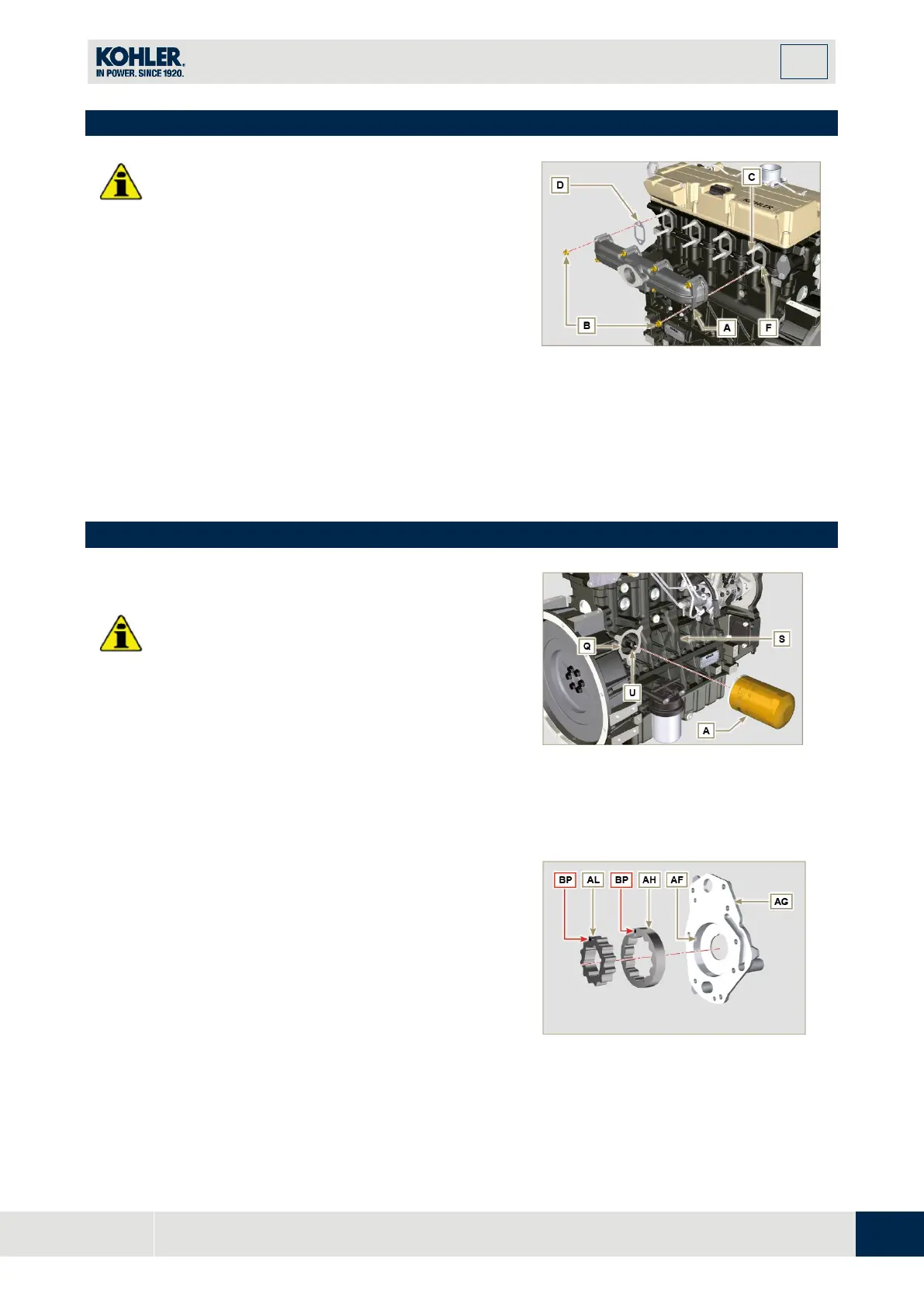
9.10 Exhaust manifold assembly
•
Replace the self-locking nuts B and the metal
gaskets D between the manifold and the cylinder
head every time they are assembly.
•
In the event of mounting the studs C, fix (25 Nm
tightening torque) with Loctite 2701 on the thread.
1.
Check that the contact surfaces F are free from
impurities.
2.
Insert the gaskets D and E on the studs C.
3.
Position the manifold A on the studs C.
4.
Fix the manifold A on the cylinder head by
tightening the self-locking nuts B (tightening torque
of 25 Nm).
Fig 9.71
9.11 Lubrication circuit assembly
Important
•
In the event of mounting the fitting U on the
crankcase S, fix (15 Nm tightening torque) wi
th
Loctite 2701 on the thread.
1.
Check that the surface Q on crankcase S are fr
ee
f
rom impurities.
2.
Screw the cartridge A on the fitting U (tightening
torque at 15 Nm).
Fig 9.72
N
OTE:
Carry out the checks described in
Par. 8.7
before
proceeding with the following operations.
1.
Check that all contact surfaces between AL, AH
,
AF
, AG and AN are free of impurities – scratches -
dents.
2.
When assembling, do not use any type of gasket
between AG and AN.
3.
Thoroughly lubricate the seat of the rotors AF on
t
he oil pump crankcase AG and the two rotors AH
and AL.
Fig 9.73

 Loading...


