9
ASSEMBLY INFORMATION
EN 132
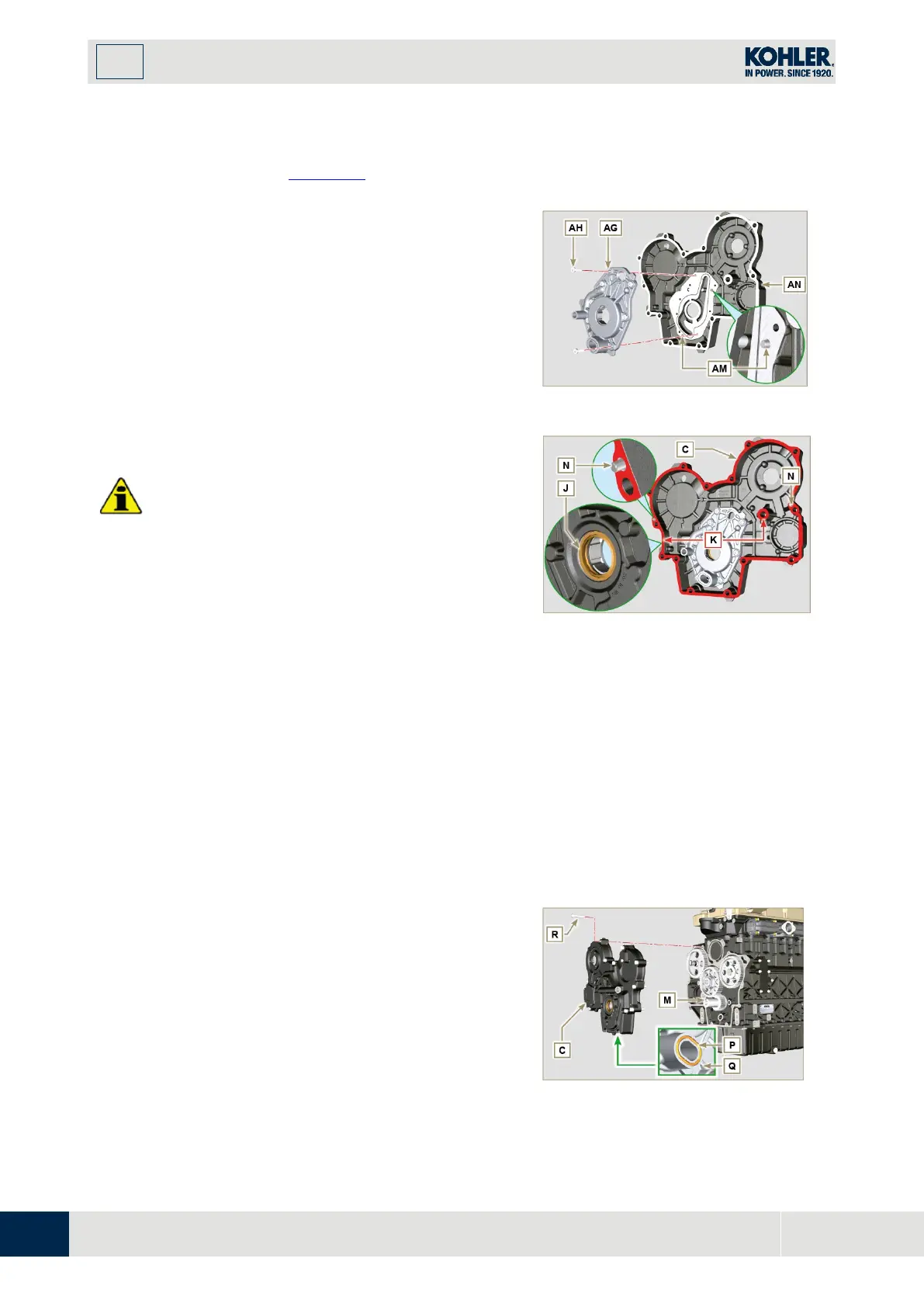
Insert, inside the seat AF, the 2 rotors (in sequence)
AH and AL, respecting the reference BP as the
picture. (or refer to Par. 2.10.2).
5.
Check that the 2 pins AM are inserted properly in
the crankcase timing system AN.
6.
Position the oil pump assembly AG using the pi
n
marks AM.
7.
Fasten the oil pump cover AG with the screws AH
(tightening torque 10 Nm).
9. 11.3 Timing system crankcase
Important
•
Always replace the oil seal J after each assembly
(ST_14).
•
Always replace the gasket P after each assembly.
• To prepare the surface of the K plane for the new
application of the sealant, it must be cleaned
through the use of:
- initially Loctite SF 7200
- subsequently Loctite SF 7063
Avoid any contact with the K plane and be careful
not to compromise the cleaning performed.
1.
Distribute a bead of Loctite 5188, of about 1mm
thickness, on the surfaces K of the crankcase C.
2.
Make sure that the key M (Fig. 9.76) is inserted
properly on the crankshaft and that it is facing
upwards.
3.
Lubricate and insert the gasket P in the seat of oil
pump Q.
Fig 9.75
4.
Tighten the tool ST_10 on the crankshaft.
5.
Check that the 2 pins N are properly inserted in th
e
timing system crankcase C.
6.
Lubricate the gasket J with oil and position the
crankcase C on the crankcase E, using the pins N,
inserting the oil pump Q on the crankshaft.

 Loading...


