INFORMATION ABOUT OPTIONAL
COMPONENTS
11
171
EN
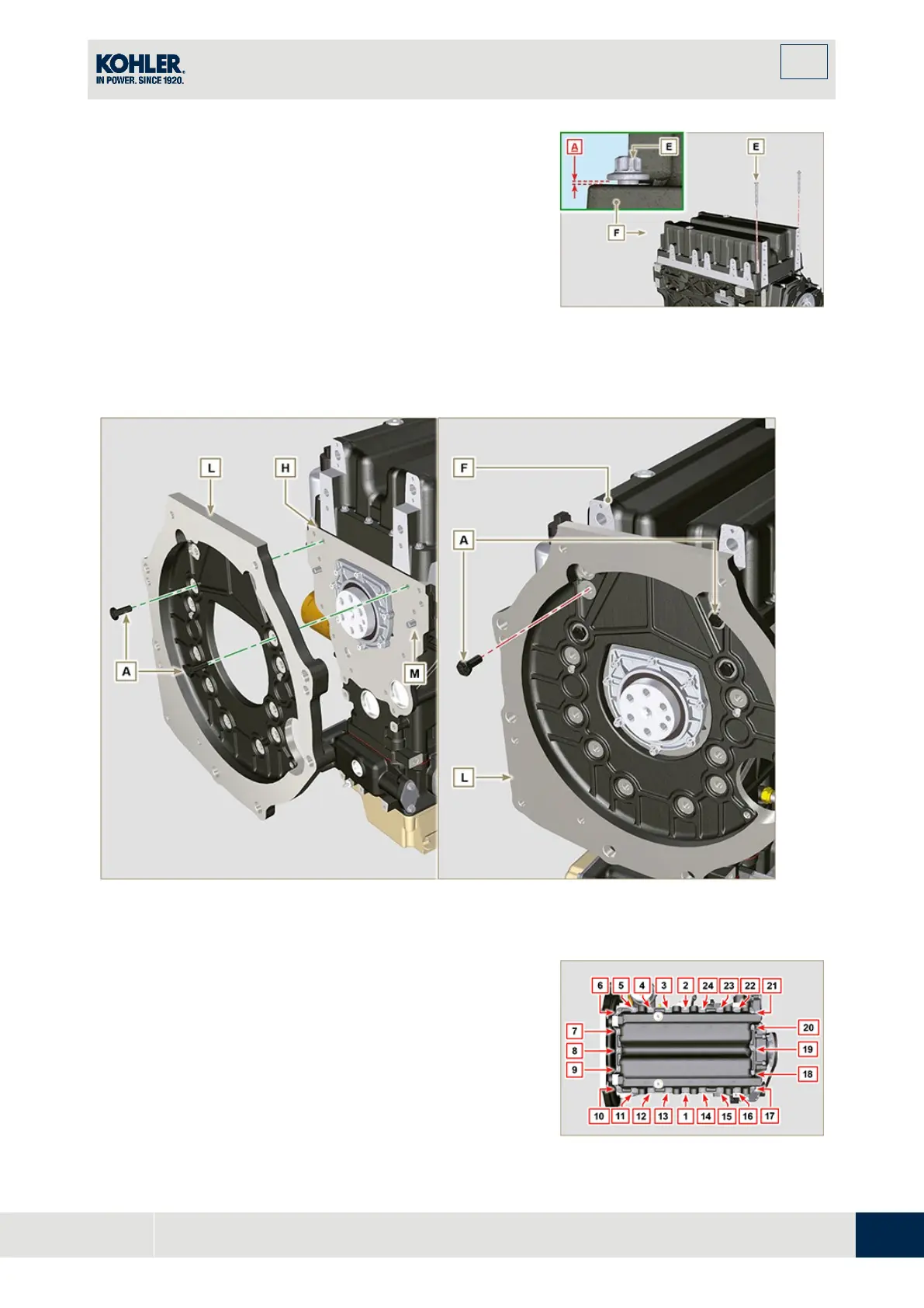
Apply capscrews
into the fastening holes and use
torque at 10 Nm.
5.
Loosen capscrews E, leaving approximately 1 mm
leeway (position A) between the neck surface o
f
capscrews E and oil sump F.
6.
Place flange housing or plate L onto crankcase H,
complying with centring tap pins M.
7.
Using 2 capscrews A, fasten housing or plate L onto
crankcase H (tightening torque at 20 Nm).
8.
Using 2 capscrews A, fasten housing or plate L onto
oil sump F (tightening torque at 20 Nm).
Fig. 11.76
Fig. 11.77
9.
Fasten oil sump F by tightening capscrews E an
d
s
trictly following the order shown in Fig. 11.77
(tightening torque at 20 Nm).
10.
Loosen capscrews A and remove housing or plate L
(Fig. 11.76).
11.
Fasten oil sump F by tightening capscrews E an
d
strictly following the order shown in Fig. 11.77
(tightening torque at 47 Nm).
Loosen the screw 1 again and tighten it to 47 Nm.
Fig. 11.78

 Loading...


