9
ASSEMBLY INFORMATION
EN 118
Important
•
It is mandatory to replace the gasket B after each
assembly.
•
Always replace capscrews D with new ones or
alternatively apply Loctite 2701.
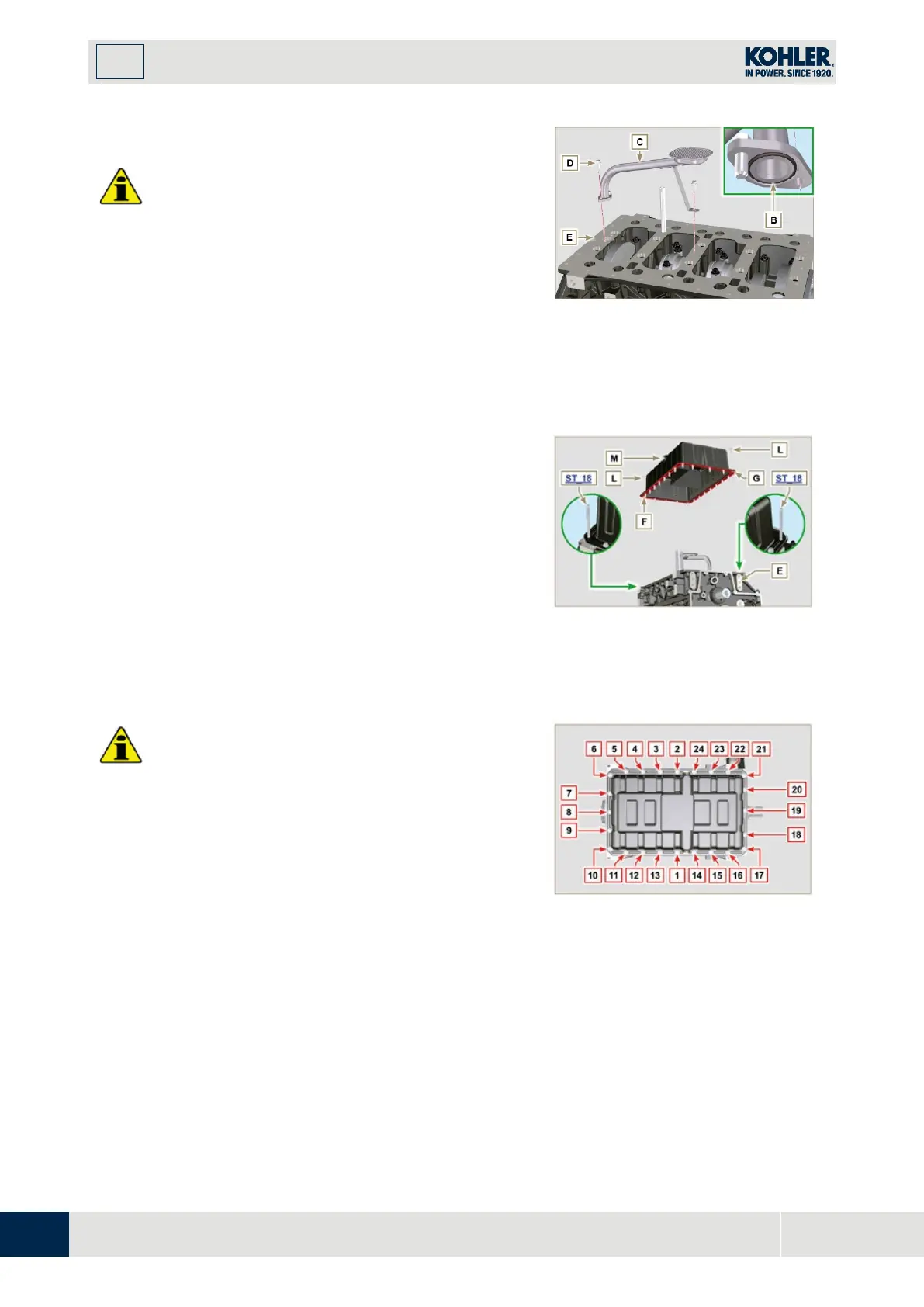
1.
Insert the new gasket B in the seat of the oil suctio
n
h
ose flange D.
2.
Secure the hose C on the crankcase E with the
screws D (tightening torque 10 Nm).
Fig 9.24
1.
Ensure that the contact surfaces F of the oil sump G
and the crankcase E are completely clean.
2.
Apply a bead of approx. 2.5 mm of sealant (Loctite
5660) on the surface F of the oil sump G.
3.
Rotate the crankshaft clockwise ST_34 tool bringin
g
r
eference X upwards.
NOTE: During the positioning phase of reference X,
check that cylinder N° 1 is in compression phase
(intake and exhaust valves of cylinder N° 1 must be in
closing position).
Fig 9.25
•
Tighten the screws L, strictly following the sequence
and tightening torque indicated.
4.
Tighten the screws L following the sequen
ce
i
ndicated (tightening torque 25 Nm).
5.
Remove the two studs ST_18 with the appropriate
screws (tightening torque 25 Nm)
6.
After tightening all of the screws, loosen screw n°1
and retighten it to the torque value specified in step
4.
7.
Check that the oil drain plugs M are tight (tightening
torque 35 Nm).
Fig 9.26

 Loading...


