ASSEMBLY INFORMATION
9
121
EN
Important
•
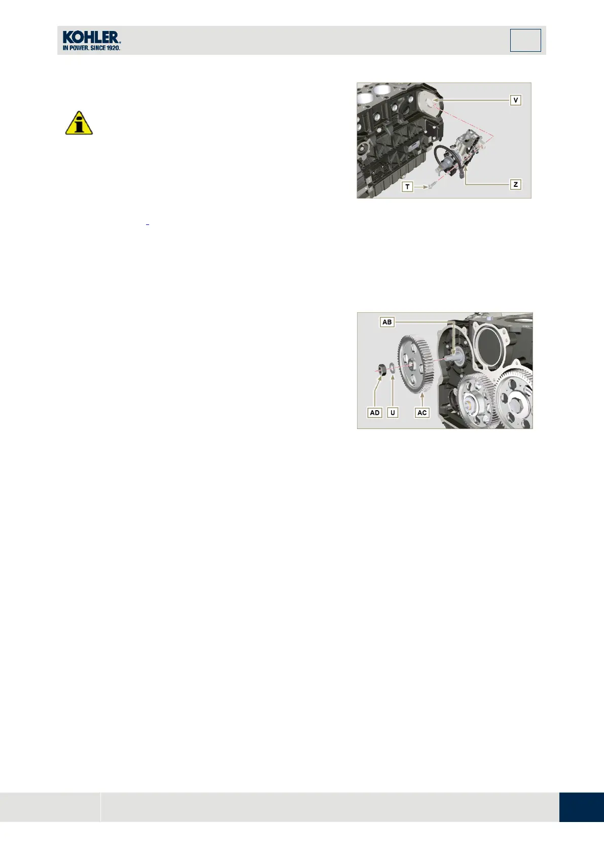
Always change screws T with new ones or
alternatively apply Loctite 270 (Fig. 9.34) to the
threads.
1.
Perform the operations described in the warning in
Par. 6.1.5.
2.
Place a dial gauge to detect the TDC on piston N° 1,
then bring the indicator of the dial gauge to 0.
NOTE
: During the detection phase of the TDC, check that
cylinder N°
1
is in compression phase (align the notches
W
as in
Fig. 9.33
).
Fig 9.34
By means of the identified pump code, refer to Tab.
6.1 to know the advance degrees and th
e
c
orresponding value to lower the piston.
4.
Mount tool ST_34 in the seat of starter motor
H
(
Fig. 9.29) and fix it with two motor fixing screws.
5.
Having identified the value to lower the piston,
rotate the crankshaft anti-clockwise by goin
g
b
eyond the value described in Tab. 6.1, once again,
rotate the crankshaft clockwise stopping at the
correct advance value by using tool ST_03 - ST_34.
6.
Lock the ST_34, ensure that the crankshaft does
not rotate, which would alter the correct advan
ce
v
alue.
If this happens, repeat the instructions described i
n
p
oints 4, 5 and 6.
Fig 9.35

 Loading...


