ASSEMBLY INFORMATION
9
123
EN
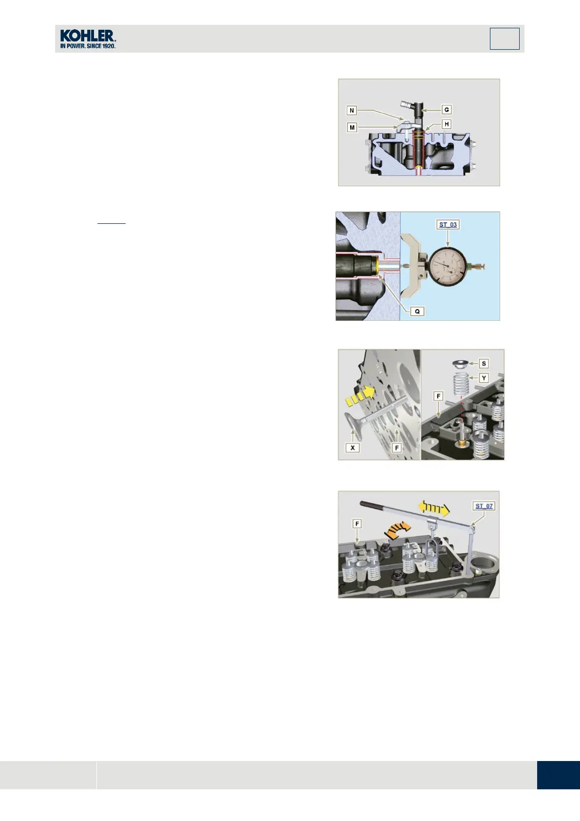
9.7.3 Injectors projection
1.
Insert the injector G inside the sleeve H.
2.
Mount the injector fixing bracket M and secure it
with the screw N, without performing the
calibration.
3.
Check protrusion of injectors by means of the tool
ST_03
(
Fig. 9.44), check the projection of the
injector, which must range between 1.68 ÷ 2.42
mm.
NOTE: if the value detected does not correspond, replace
gasket Q with a different thickness.
Fig 9.40
9.7.4 Valves
1.
Pre-lubricate and insert the valves X into the head
F taking care to fit them in the original positions as
per the reference marks made in Par. 7.13.4.1.
2.
Position the spring Y on the seat of the head F.
3.
Position the disk S on the spring Y centering the
valve X.
4.
Mount the tool ST_07 on the head F fixing it on
one of the holes for securing the rocker arm cover.
NOTE: Change the fixing hole according to the position of
the valves to be fitted.
5.
Position the tool ST_07 on the valve as shown i
n
the
figure.

 Loading...


