9
ASSEMBLY INFORMATION
EN 124
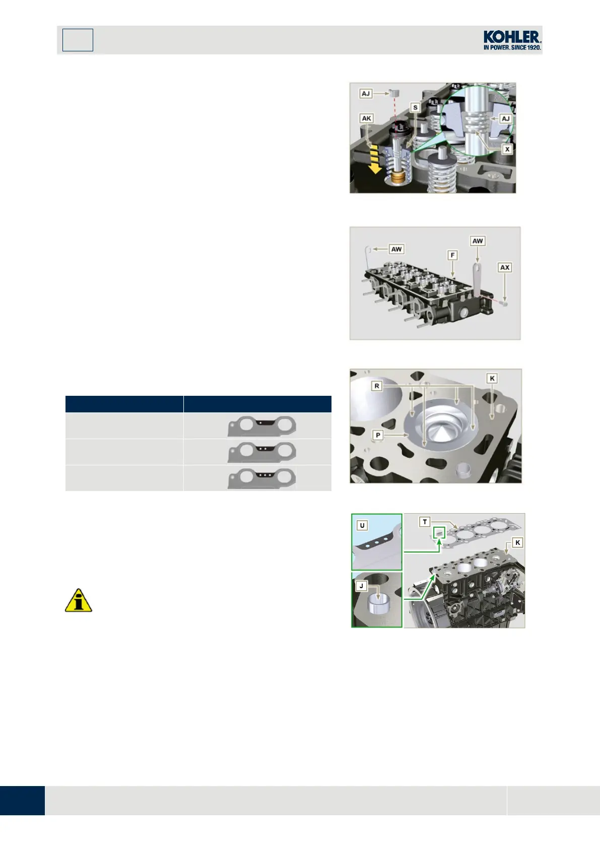
Push the lever of the tool ST_07 downwards, in
order to lower the valve disks S in the direction of
the arrow AK, and insert the valve cotters AJ
inside the disk S.
7.
Check that the valve cotters AJ are properly
mounted on the valve seats X and release the tool
ST_07
.
NOTE: repeat all the steps for the relevant valves and
F
ig 9.44
1.
Fix the eyebolts AW with the screws AX onto the
head F (tightening torque of 25 Nm).
2.
Position the piston P at the TDC.
3.
Position the tool ST_03 on the crankcase surfa
ce
o
f the head and measure the piston protrusion P
from head level K in 4 diametrically opposed points
R. Repeat the operation for all pistons P and take
n
ote of the highest average value, determining valu
e S (Tab. 9.2).
Tab. 9.2
0.030 - 0.126
1
0.127 - 0.250
2
0.251 - 0.375
3
4.
Based on the value detected at point 3, select th
e
r
elevant gasket T as shown in the Tab. 9.2 (Fig.
9.47 detail U).
5.
Check that the crankcase surface K and the gaske
t
T ar
e completely free of dirt and grit.
I
mportant
•
The head gasket must be replaced for each
assembly.
6.
Position the gasket T on the surface K wi
th
r
eference to the centering bushings J.
Fig 9.45
F
ig 9.46
F
ig 9.47

 Loading...


