11
INFORMATION ABOUT OPTIONAL
COMPONENTS
EN 174
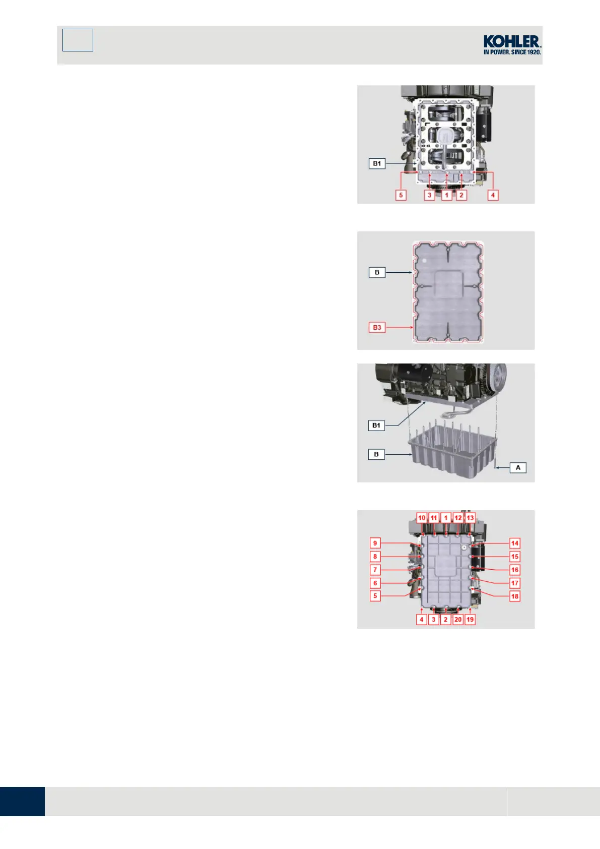
4.
To fix the sump B1 , tighten the screws A1 by strictl
y
following the order indicated in the Fig. 11.83
(tightening torque of 25 Nm ).
5.
Loosen the screw 1 again and tighten it to 25 Nm .
Fig. 11.83
6.
Apply a bead of approx. 2.5 mm of sealant ( Loctite
5660 ) inside the channel B3 of the oil sump B .
7.
Position the oil sump B on the oil sump B1 flange at
the fixing holes (use the tool ST_18 ).
8.
Screw the screws A in the fixing holes.
Fig. 11.84
9.
To fix the sump B , tighten the screws A by strictl
y
f
ollowing the order indicated in the Fig. 11.85
(tightening torque of 25 Nm ).
10.
Loosen the screw 1 again and tighten it to 25 Nm .
Fig. 11.85

 Loading...


