INFORMATION FOR DISASSEMBLY
7
89
EN
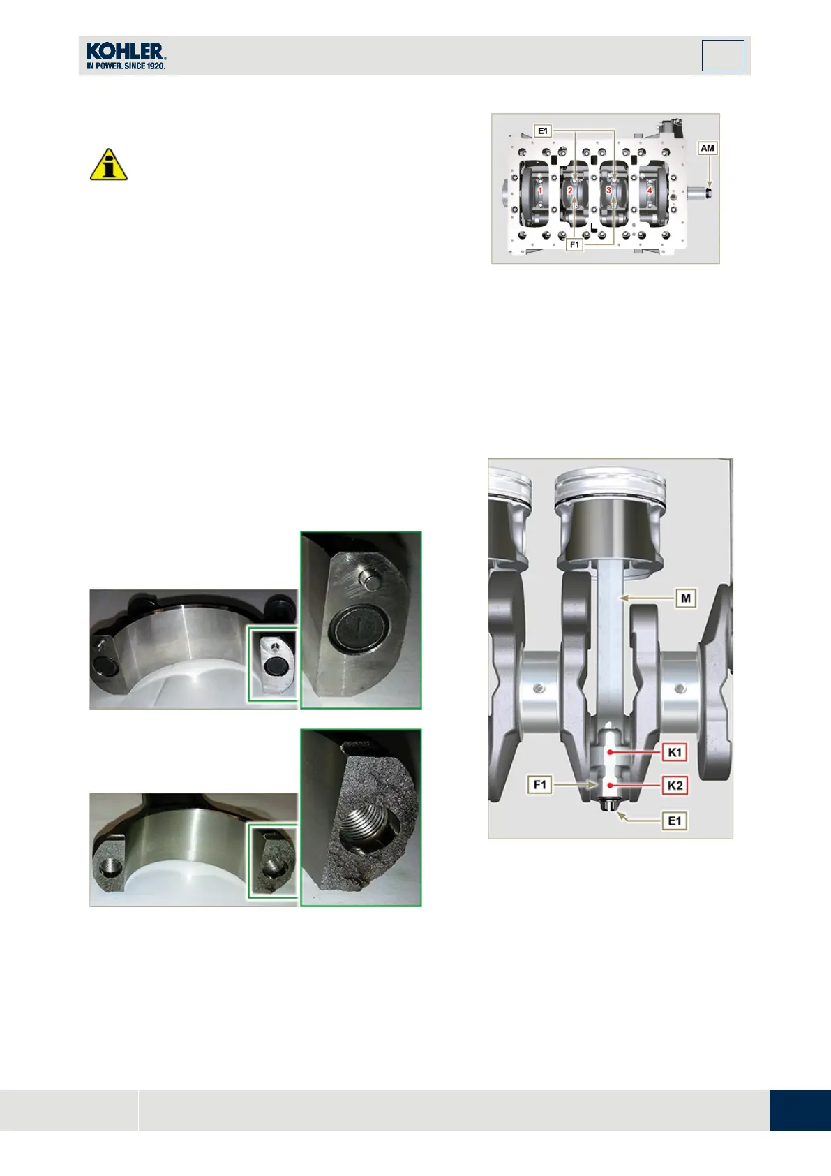
7.13.2 Piston unit/connecting rod
Important
•
Mark some numerical references (cylinder n°) on th
e
c
onnecting rods, connecting rod caps F1, pistons
and gudgeon pins to prevent unintentionally
confusing the components not replaced during
assembly. Failure to do this may result in engine
malfunctions.
•
References on connecting rod M and cap F1 mus
t
o
nly be carried out on a side in corresponden
ce
w
ith K1 and K2, as illustrated in Fig. 7.46a.
1.
Screw the bolt AM temporarily.
2.
Unsrew bolts E1 and remove the connecting rod
caps F1.
Fig 7.46
NOTE
: coupling cap
F1
on the connecting rod can be
carried out with centring taper pins
(Fig. 7.46b)
or broken
(
Fig. 7.46c
- without centring taper pins).
Fig. 7.46b
Fig. 7.46c
Fig 7.46a

 Loading...


