Optical components page 27
6 Optical components
6.1 Connecting the camera
The instrument comes with a camera already assembled in the camera housing of
the DSA100. The camera must be connected to the frame grabber board of the
computer.
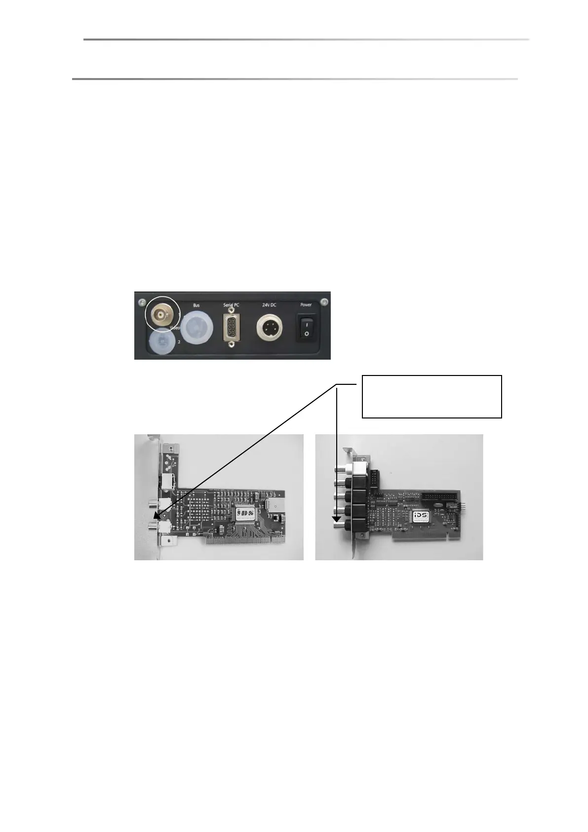
CF3200/3201
Connect the Video connection on the rear side of the camera to the frame-
grabber board of the computer. Use the supplied BNC cable.
CF3220
Connect the cable with the Camera Link plug (coming from the DSA100 panel)
to the connection Channel 0 of the frame grabber board.
IEEE-1394 cameras
Connect the IEEE-1394 connector at the rear side of the DSA100 housing to the
right-hand connection of the IEEE-1394 interface board of the computer.
Only use the delivered IEEE-1394 interface board for connecting the camera and
no other IEEE-1394 interface.
SPAC S PA C S PAC S PAC
Connection with channel 1 for
Falcon (left) or Falcon Plus
(right)