A
B
ENGINE/ CRANKSHAFT
77
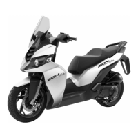
4. Measure the run-out at the bearing pins of the crankshaft.
Allowable Limit (A/B): 0.1 mm
5. Check the crankshaft bearings for excessive play. The bear-
ings must be replaced if they are noisy or have excessive
play.
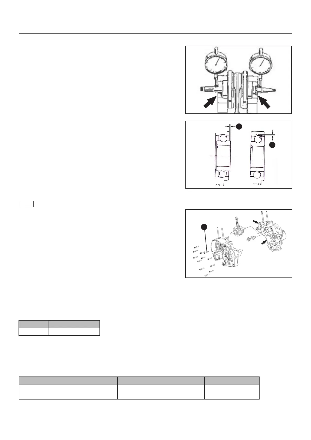
NOTE
If the crankshaft, transmission shaft and balance shaft installed
in the left crankcase put some surface sealant thin on the plane
surfaces of the left crankcase (arrow). Please note that there is
no separate gasket available.
Installation of right crankcase should work smooth and without
additional force. Watch out the shafts move to the right position
before xing the crankcases with screws. Disassemble and as-
semble again if the engine parts do not t together smooth.
If necessary heat up the right crankshaft bearing before assem-
bling.
Tighten all screws (1) with the specic torque in reversed order
of disassembling.
Do not forget the screw on the right engine side.
TROUBLESHOOTING
TORQUE LIST
PART NO. TORQUE
1 10 - 12 Nm
1
FAILURE CAUSE TO DO
Noise out from the crankcase
Loosen or damaged parts (bear-
ings, gears,....) in the crankcase
Replace
 Loading...