ENGINE/ TOP END
79
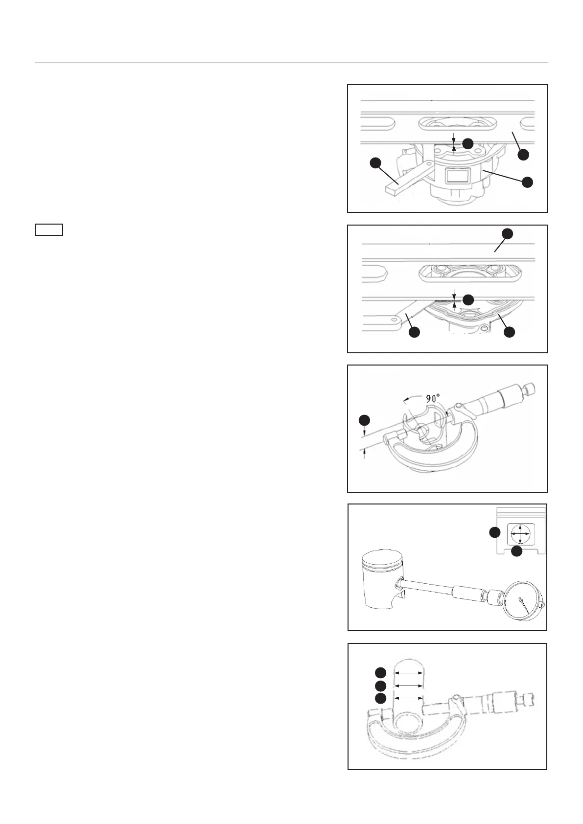
1. Inspect the atness of the cylinder. (1. Ruler, 2. Measuring
gauge, 3. Cylinder)
Allowable limit A: 0,05 mm
NOTE
Inspect the cylinder head in the same way.
2. Inspect the atness of the cylinder head. (1. Ruler, 2. Meas-
uring gauge, 3. Cylinder head)
Allowable limit B: 0,05 mm
3. The measuring position and the piston pin form an angle of
90 degree, and 15.5mm (C) below the skirt of piston.
Allowable limit C: 40.2 mm
4. Measure the bore diameter of the piston pin hole. Measure
both X and Y directions.
Allowable limit X/Y: 12.04 mm
5. Measure the outer diameter of the piston pin at three levels
of A, B and C.
Allowable limit: 11.96 mm
X
Y
A
B
C
A
1
2
3
B
2
3
1
C
 Loading...