Operating Instructions
14 of 206
BA KR 6, 16 F, KR C4 12.10.07 en
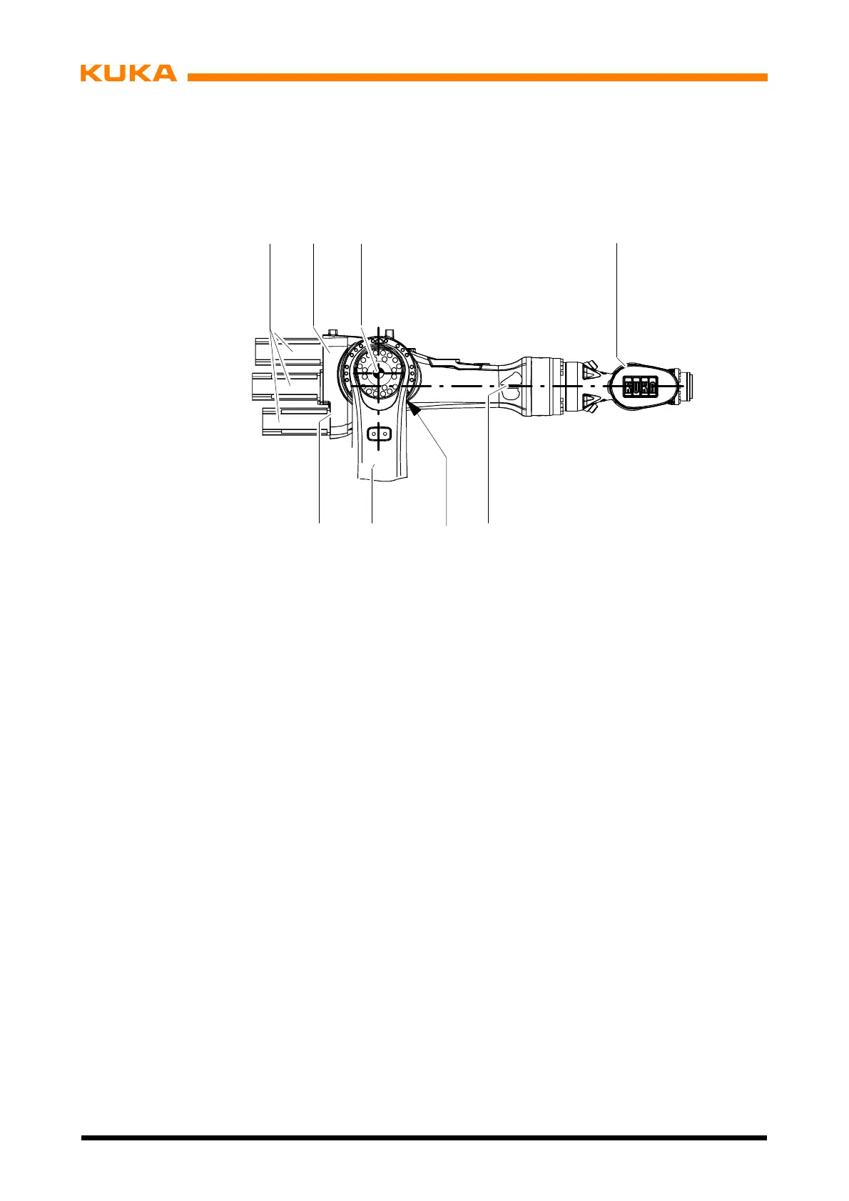
Mounted on the front end of the arm via a standardized interface is the in--line wrist (4), which
is driven by the motor units (1) via push--on shafts (5) located inside the arm. For attaching
supplementary loads, the arm is equipped with four tapped holes on its top side.
1 Motor units for wrist axes 6 Main axis motor unit A3
2Arm 7Linkarm
3 Rotational axis A3 8 Arm housing
4 In--line wrist
5 Shaft
12 3
567
8
4
Fig. 4 Arm
 Loading...


