Operating Instructions
64 of 206
BA KR 6, 16 F, KR C4 12.10.07 en
6.2 Floor--mounted manipulators
Information!
Please observe Section 6.1.
The manipulator can be transported as follows:
G With lifting tackle and crane (Fig. 41, left--hand side)
The manipulator can be suspended from the hook of a crane by means of lifting tackle at-
tached to three eyebolts on the rotating column.
Caution!
The ropes or belts of the lifting tackle must be positioned so that there is no
possibility of the manipulator tilting to the side and of cabling or connectors
being damaged.
Caution!
Only approved handling equipment and lifting tackle with an adequate carrying
capacity may be used for transporting the manipulator .
For the weight of the manipulator, see Chapter 4, “Technical data”.
All three eyebolts on the rotating column must always be used to suspend the
robot.
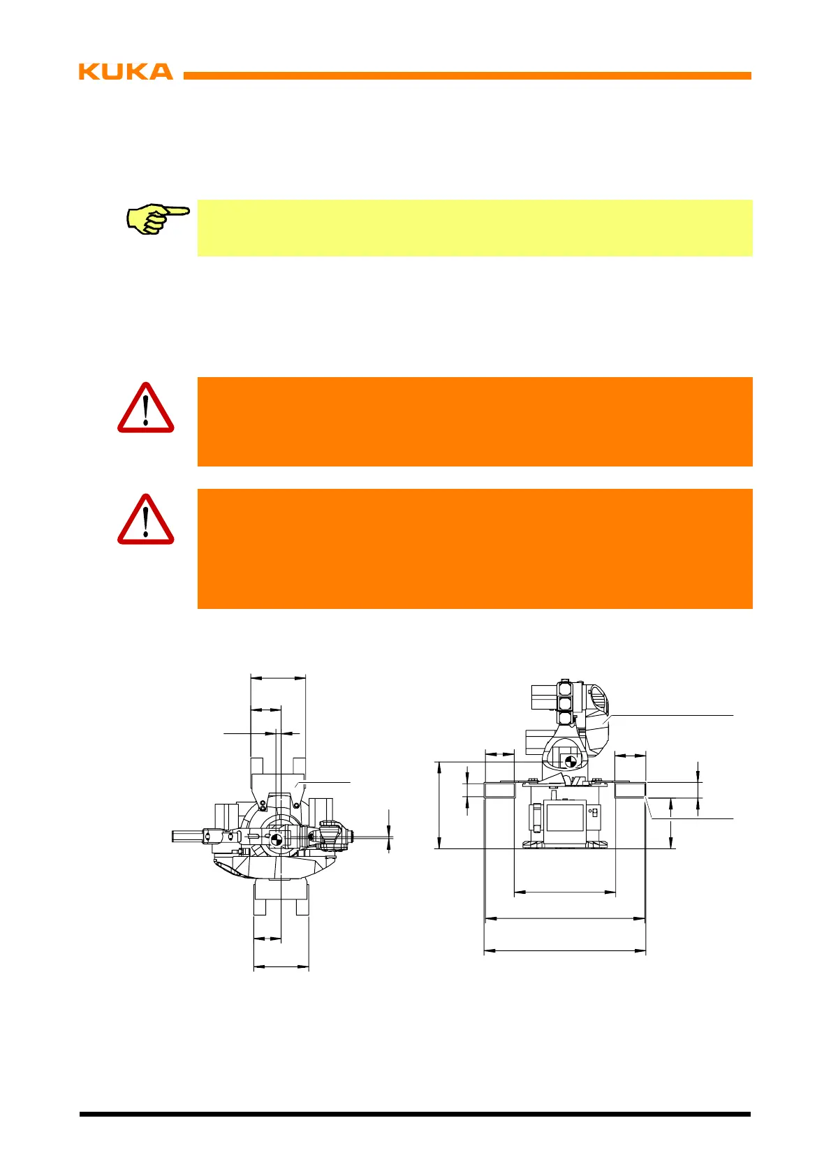
G With fork lift truck (Fig. 41, right--hand side)
1
2
2
+
184
200
100
552
1030
(646)
1014
84
322
+
180
19
7
360
360
200
Fig. 40 Fork slots
For transportation with a fork lift truck, two removable, open--ended fork slots (Fig. 40/2) are
mounted on the rotating column. This allows the manipulator (1) to be picked up from two
sides.
 Loading...


