3 Product description (continued)
21 of 206
BA KR 6, 16 F, KR C4 12.10.07 en
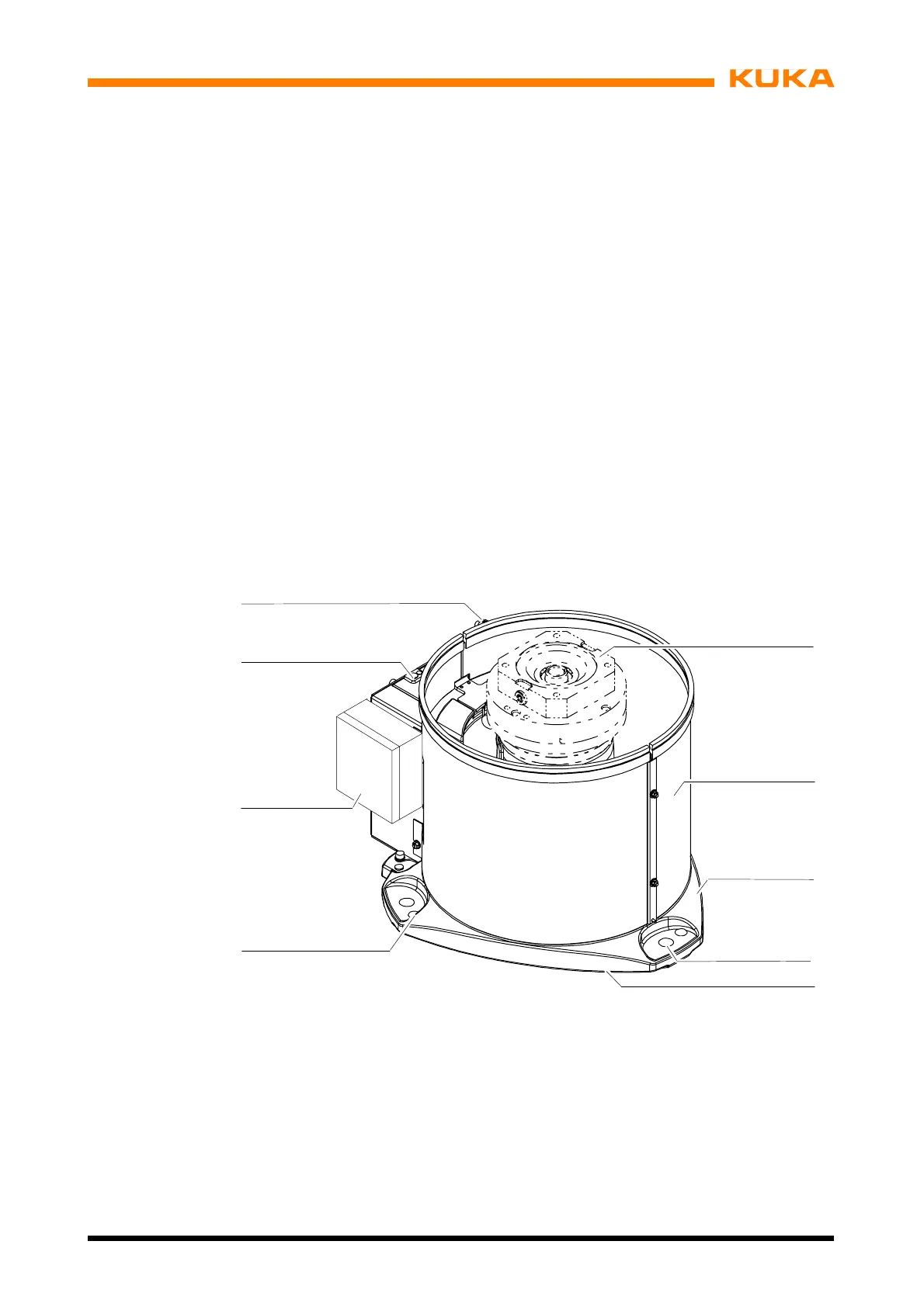
3.6 Base frame
The base frame (Fig. 11) is the stationary part of the manipulator, on which the rotating col-
umn turns with the link arm, the arm, and the wrist. Its base flange (5) features through--holes
(4) for holding the manipulator down and three locating boreholes (6), with which the manipu-
lator can be placed on two locating pins (accessories, see also Section 7.5, “Installation”).
Attached to a flange inside the base frame housing (3) is the gear unit (1) of axis 1. Also inte-
grated into this flange is the double--acting trailing stop, which together with a stop block on
the rotating column mechanically safeguards the software--limited movement range of 370°
about rotational axis A1.
In the base frame, the installation cables leading to the rotating column are routed stress--
free about rotational axis A1 of the manipulator in a flexible tube. The space between the
rotating column and the base frame is provided with a detachable, two--piece cover (2).
The sockets for the connecting cables from the control cabinet to the manipulator are located
on the RDC box (7) and on the MFH (multi--function housing).
The reference notch (8) necessary for determining the mechanical zero position is found on
the housing of the base frame.
1
2
3
4
6
5
8
7
9
1 Gear unit A1 6 Locating boreholes (3x)
2 Cover 7 RDC box
3 Base frame housing 8 Reference notch
4 Fastening holes (3x) 9 MFH
5 Base flange (multi--function housing)
Fig. 1 1 Structure of base frame
 Loading...


