171 of 206
BA KR 6, 16 F, KR C4 12.10.07 en
2
3
4
5
1
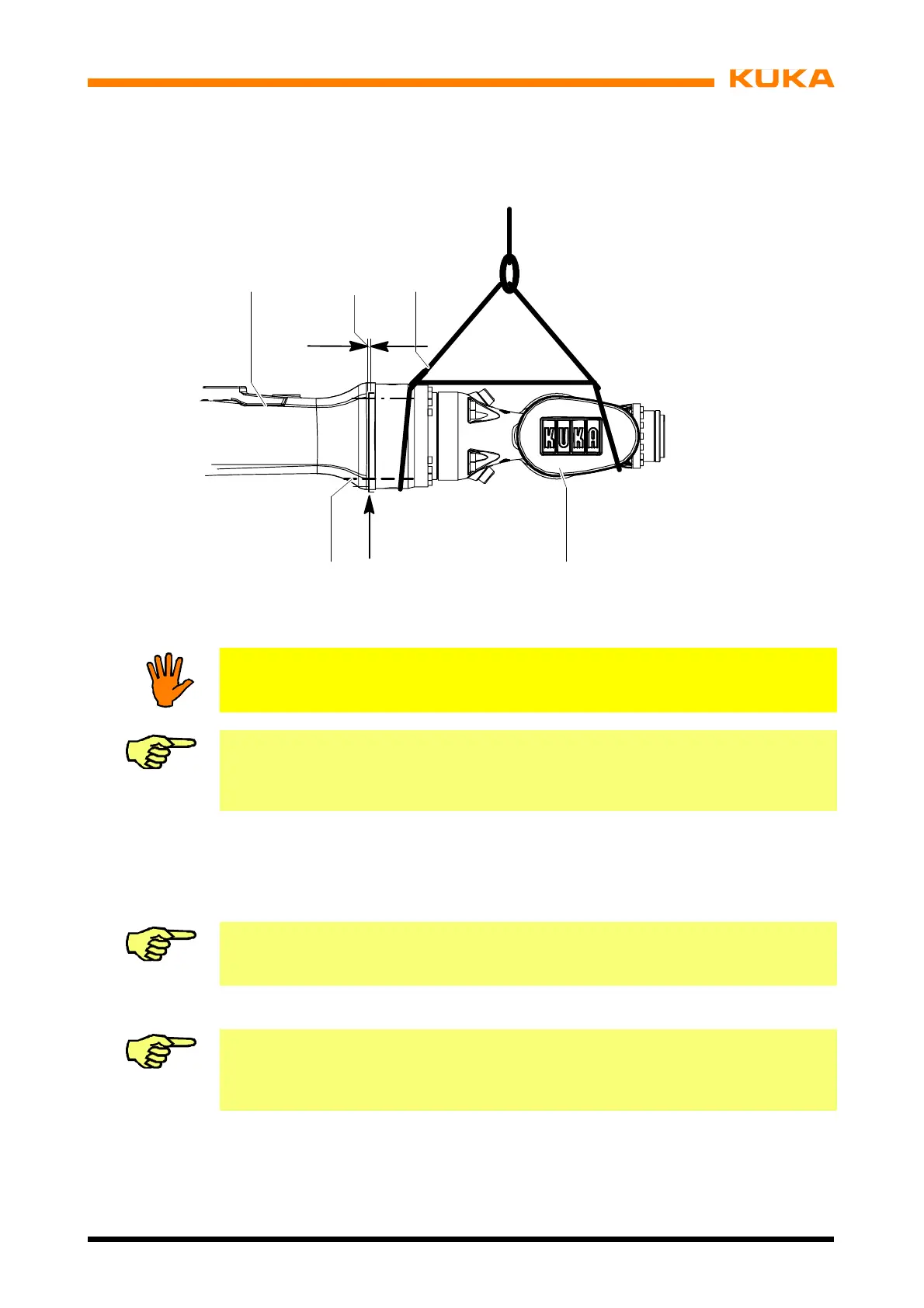
Fig. 119 Removal, installation of in--line wrist
Notice!
The in--line wrist may not be further dismantled.
Information!
If the in--line wrist is not to be reinstalled, it must be protected against corrosion before
being put into storage.
D Installation
(1) Remove all protective coatings and oil from new in--line wrist, if applicable.
Information!
Clean the shaft toothing before installation and lightly grease it with Microlube GL 261.
(2) Install the in--line wrist by carrying out the removal instructions in reverse.
Information!
When installing a new in--line wrist, it must be ensured that axes 4, 5 and 6 are in their
zero positions.
(3) Tighten the 16 M6x90--10.9 Allen screws (Fig. 119/5) with a torque wrench in diagonally
opposite sequence, increasing the tightening torque M
A
in several stages to the speci-
fied value (M
A
= 12.5 Nm).
(4) Carry out zero adjustment on axes 4, 5 and 6 (see Operating Handbook, Software
KR C4, Chapter “Start--up”, Section “Robot Mastering/Unmastering”).
 Loading...


