187 of 206
BA KR 6, 16 F, KR C4 12.10.07 en
D Installation (A6)
Information!
With F--variant robots, seals are fitted between the arm and the wrist axis motor units.
These must be renewed during installation. In addition, for this robot variant, Drei Bond
1108 sealant is to be used when inserting the following screws:
-- Setscrews for the holes not occupied by the adjusting screws.
When ordering wrist axis motor units, always indicate if they are for use in these robot
variants.
(1) Remove all protective coatings and oil from new motor unit A6, where applicable.
(2) Clean the involute toothing (Fig. 128/1) and apply a thin but continuous coat of Micro-
lube GL 261.
2
1
3
5
6
4
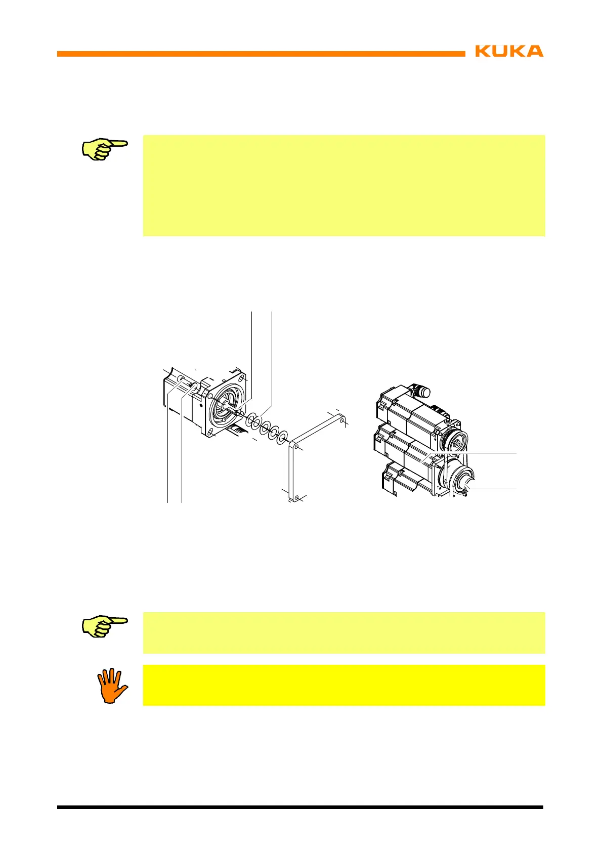
Fig. 128 Installation of motor unit A6
(3) Push the disc springs (2) onto the toothing as shown in Fig. 128.
(4) Push motor unit A6 (3) into the involute toothing of shaft A6 (4) and into the centering
flange of the arm housing.
Information!
Insert motor unit A6 so that connectors XM6 and XP6 are on the left.
Notice!
The shaft stub of motor unit A6 must not be subjected to any axial loads.
(5) Insert four M15x16--8.8 Allen screws (6) including lock washers (5) and tighten with a
torque wrench in diagonally opposite sequence, increasing the tightening torque to the
specified value in several stages (M
A
= 5.6 Nm).
(6) Insert connectors XM6 and XP6.
(7) Carry out zero adjustment (see Operating Handbook, Controller, section “Robot maste-
ring/unmastering”).
 Loading...


