Operating Instructions
66 of 206
BA KR 6, 16 F, KR C4 12.10.07 en
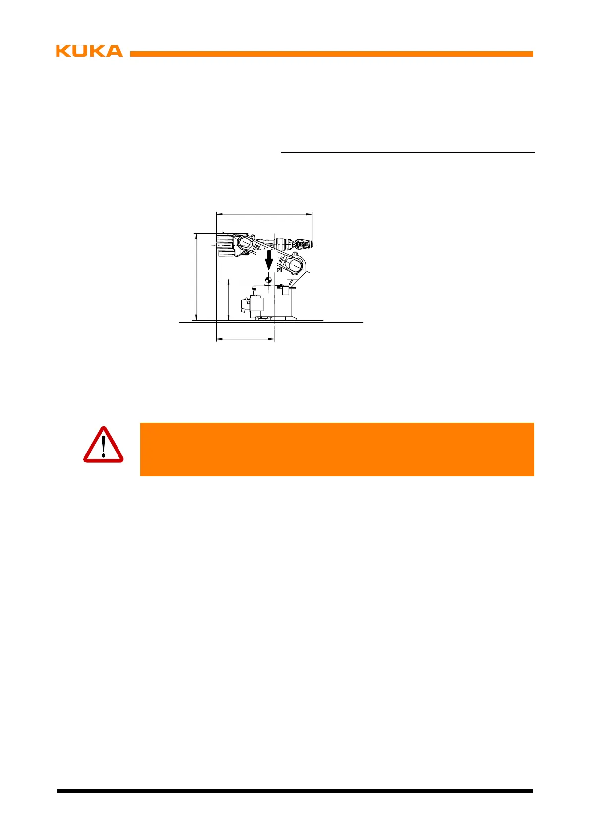
(2) Put the manipulator into operation and move it into the transport position (Fig. 42).
A1 A2 A3 A4 A5 A6
0˚
---155˚ +154˚ 0˚ 0˚ 0˚ *
ll angles are speci
ied relative to the electrical “zero position” or
to the KCP display.
1078
G = 235 kg KR 6, KR 16
240 kg KR 16 L6
552
G
19
1115
1)
1184
2)
1416
3)
686
1)
711
2)
686
3)
1)
KR 6
2)
KR 16
3)
KR 16 L6
Fig. 42 Transport position for floor --mounted manipulators
Warning!
Turn main switch on the manipulator control cabinet to “OFF” and secure it with
a padlock to prevent unauthorized persons from switching it on again.
For further work steps, see Chapter 7.5, “Installation, Connection, Exchange”.
 Loading...


