204
8 Options
8.3.2 LEDs
The VSM100 has 5 LEDs which should be connected as described below:
NOTICE
If a functional error occurs at VSM, the ERR (LED 1) red is ON, PWR (LED 2) green and CAN
(LED 3) are OFF.
Incorrect adjusted dip-switches 4 to 7 may cause this fault.
BT300 generates fault 807.
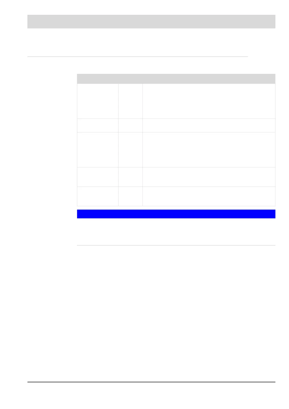
LED Colour Relevance
ERR (LED1) red During normal operation LED is switched off. It will light up
subject to following conditions:
- Initialisation incomplete or not yet successfully com-
pleted (e.g. HW could not be initialised)
- No messages received for at least 3 s.
PWR (LED2) green ON: Module working in normal mode = fully initialised and
without any fault.
CAN (LED3) green OFF: CAN Controller in Bus OFF. No communication possi-
ble.
Blinking: CAN Controller discovered temporary fault.
After fixing the problem LED will still blink for some time.
ON: CAN is ready to operate.
Namur (LED4) yellow Blinking: LED will always be toggled soon as an impulse
reaches Namur input. LED will blink with half the impulse
frequency.
3-wires (LED5) yellow Blinking: LED will always be toggled as soon as an
impulse reaches 3-wire input. LED will blink with half the
impulse frequency.

 Loading...


