214
8 Options
8.5.1.2 LEDs
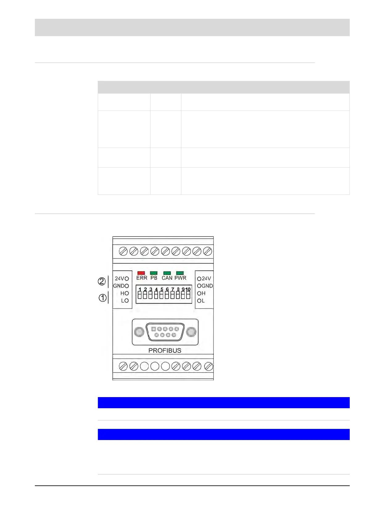
PBM100 has 4 LEDs which are connected as described below:
8.5.1.3 Electrical Connection
NOTICE
It is prohibited to use the terminals!
NOTICE
You will find wiring, cable length and definition of the interface in the respective documentation
of the field bus systems:
LAMTEC SYSTEM BUS LSB – print no. DLT6095
PROFIBUS – print no. DLT6100
LED Colour Description
PWR green ON: Module working in normal mode = fully initialised and
without any fault.
CAN green OFF: No communication or CAN BUS error
Blinking with 2 Hz: Errors (optional, if a CAN warning is
detectable)
ON: CAN is ready.
PB green OFF: no communication via PROFIBUS DP
ON: communication without error via PROFIBUS DP
ERR red OFF: no errors
ON: PBM100 Initialisation incomplete or not yet success-
fully completed or CAN message missing for more than 3 s.
Terminals may not be connected!
1 CAN/LSB
2 DC power supply
(safety extra low voltage)
Terminals may not be connected!

 Loading...


