LNC-Lathe New T6-Series
CNC Operation
LNC Technology Co., Ltd. 59
⊙ Tool NO.:tool parameter number, The same type, able to do CAM calculation according to difference
parameter. Selecting the NO. 1 tool parameter when one tool is at the first procedure. But,
for the 2
nd
procedure, users can select the 2
nd
tool parameter for CAM calculation.
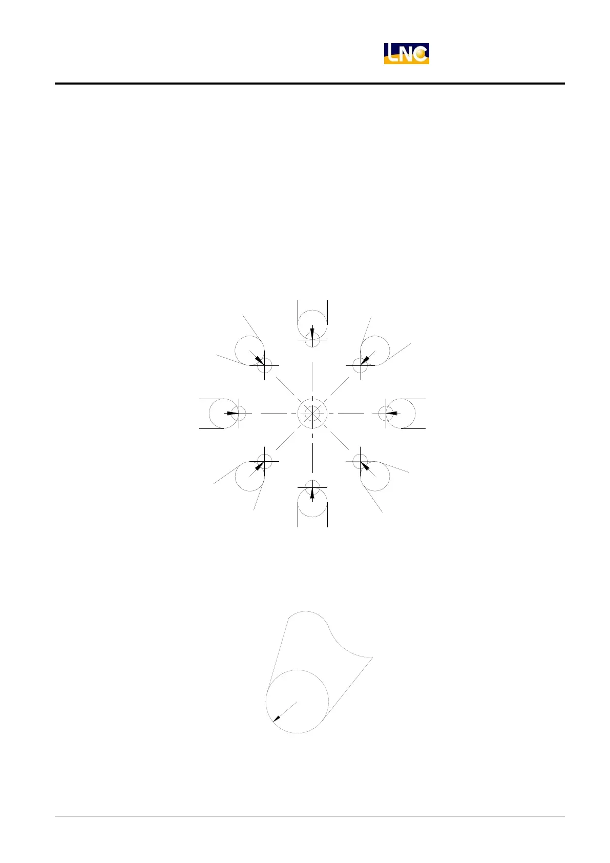
⊙ Tool Direction:tool noise direction, which is the imagery tool tip direction. Using 10 numbers (number 0
~9) to indicate the corresponding position of the imagery tool tip and tool noise center
point. Like Figure 2.6-5, arrowhead position is the tool tip point. Tool tips of imagery Tool
# 0 and #9 is overlap with tool noise center point.
nose number 6
lmaginary tool
nose number 2
lmaginary tool
lmaginary tool
nose number 7
nose number 3
lmaginary tool
lmaginary tool
nose number 4
nose number 5
lmaginary tool
lmaginary tool
nose number 1
nose number 8
lmaginary tool
lmaginary tool
nose number 0,9
lmaginary tool nose
Figure 1.6-5 Corresponding Position Figure of Imagery Tool Tip Point and Tool Noise Center Point
⊙ Tool Radius: tool noise radius. The below Figure is the tool tip after scaling in.
Figure 1.6-6 Scale-In Figure of Tool Tip
 Loading...