ppendix ProtoMat S
98 HB V0.9/Mrz-11 © 2011 LPKF AG
10
Pos: 37 /ED_Technisc he_Dokumentation/2_Be dienungsanleitun g/Maschine/RP_Fräsb ohrplotter/Pr otoMat_S_Serie/Pr otoMat_S_Serie_II G/Kapitel_10_Anhang/ 10_3_Abbildungs verzeichnis @ 0\mod_12 55680605341_2058.doc x @ 3972 @ 2
10.3 List of figures
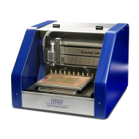
Fig. 1: ProtoMat S series ..................................................................................... 9
Fig. 2: Type plate ............................................................................................... 10
Fig. 3: Front view ............................................................................................... 26
Fig. 4: Back view ................................................................................................ 27
Fig. 5: Interfaces ................................................................................................ 27
Fig. 6: Working table .......................................................................................... 28
Fig. 7: Vacuum table .......................................................................................... 28
Fig. 8: Mill/drill head ProtoMat S43 .................................................................... 29
Fig. 9: Mill/drill head ProtoMat S63/S103 .......................................................... 30
Fig. 10: Tool holder unit ..................................................................................... 31
Fig. 11: Camera ................................................................................................. 31
Fig. 12: Required space..................................................................................... 41
Fig. 13: Transport lock ....................................................................................... 43
Fig. 14: Connections .......................................................................................... 44
Fig. 15: Start-up Logo ........................................................................................ 45
Fig. 16: Dummy tool automatically or mechanic lock ........................................ 46
Fig. 17: Startup image ....................................................................................... 48
Fig. 18: Check active tool .................................................................................. 49
Fig. 19: User interface ....................................................................................... 50
Fig. 20: Menu bar ............................................................................................... 51
Fig. 21: Function bar .......................................................................................... 52
Fig. 22: Window Processing .............................................................................. 53
Fig. 23: Control of mill/drill head ........................................................................ 54
Fig. 24: Select head ........................................................................................... 55
Fig. 25: Operate ................................................................................................. 56
Fig. 26: Move to Position ................................................................................... 57
Fig. 27: Various .................................................................................................. 58
Fig. 28: Select circuit board plotter .................................................................... 59
Fig. 29: Connect ................................................................................................ 59
Fig. 30: Connection ............................................................................................ 60
Fig. 31: User interface ....................................................................................... 60
Fig. 32: Control .................................................................................................. 61
Fig. 33: Machining view ..................................................................................... 62
Fig. 34: Tool exchange ...................................................................................... 63
Fig. 35: Tool setup ............................................................................................. 63
Fig. 36: Tool holder ............................................................................................ 64
Fig. 37: Machining view select tool .................................................................... 66
Fig. 38: Adjust position ...................................................................................... 66
Fig. 39: Control milling/drilling head .................................................................. 66
Fig. 40: Mill/drill head ......................................................................................... 70
Fig. 41: Optimal milling depth ............................................................................ 70
Fig. 42: Machining view select tool .................................................................... 71
Fig. 43: Set position ........................................................................................... 71
Fig. 44: Milling/drilling head control ................................................................... 71