Operation ProtoMat S
54 HB V0.9/Mrz-11 © 2011 LPKF AG
6
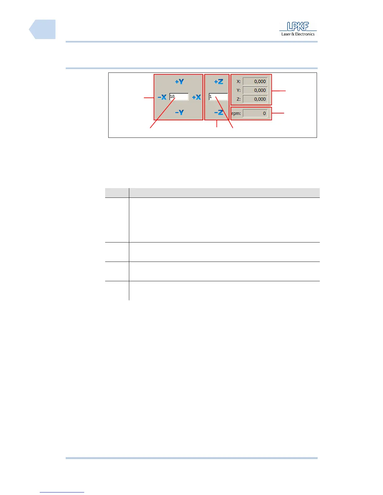
6.2.3.1 Manual control of the mill/drill head
Fig. 23: Control of
mill/drill head
/1/ Manual control X/Y direction /4/ Input field \Z step range\
/2/ Input field \X/Y step range\ /5/ Display motor speed
/3/ Manual control Z direction /6/ Display X/Y/Z coordinates
The individual buttons have the following functions:
No. Description
/1/, /2/ Type a value into the entry box \X/Y step size\ and click [-X] to move
the mill/drill head to the left side or click [+X] to move the mill/drill head
to the right side.
Type a value into the input field \X/Y step size\ and click [-Y] to move
the mill/drill head forward or click [+Y] to move the mill/drill backward.
/3/, /4/ Type a value into the input field \X/Y step size\ and click [-Z] to lift
down the mill/drill head or click [+Z] to lift up the mill/drill head.
/5/ The output field \R:\ displays the current spindle rotation speed of the
mill/drill head.
/6/ The output fields \X:\, \Y:\ and \Z:\ show the current position of the
mill/drill head.
6
1
4
5
32