UM-1151140EN, Rev. C, May 2016
System
Installation
and
Initial
Setup
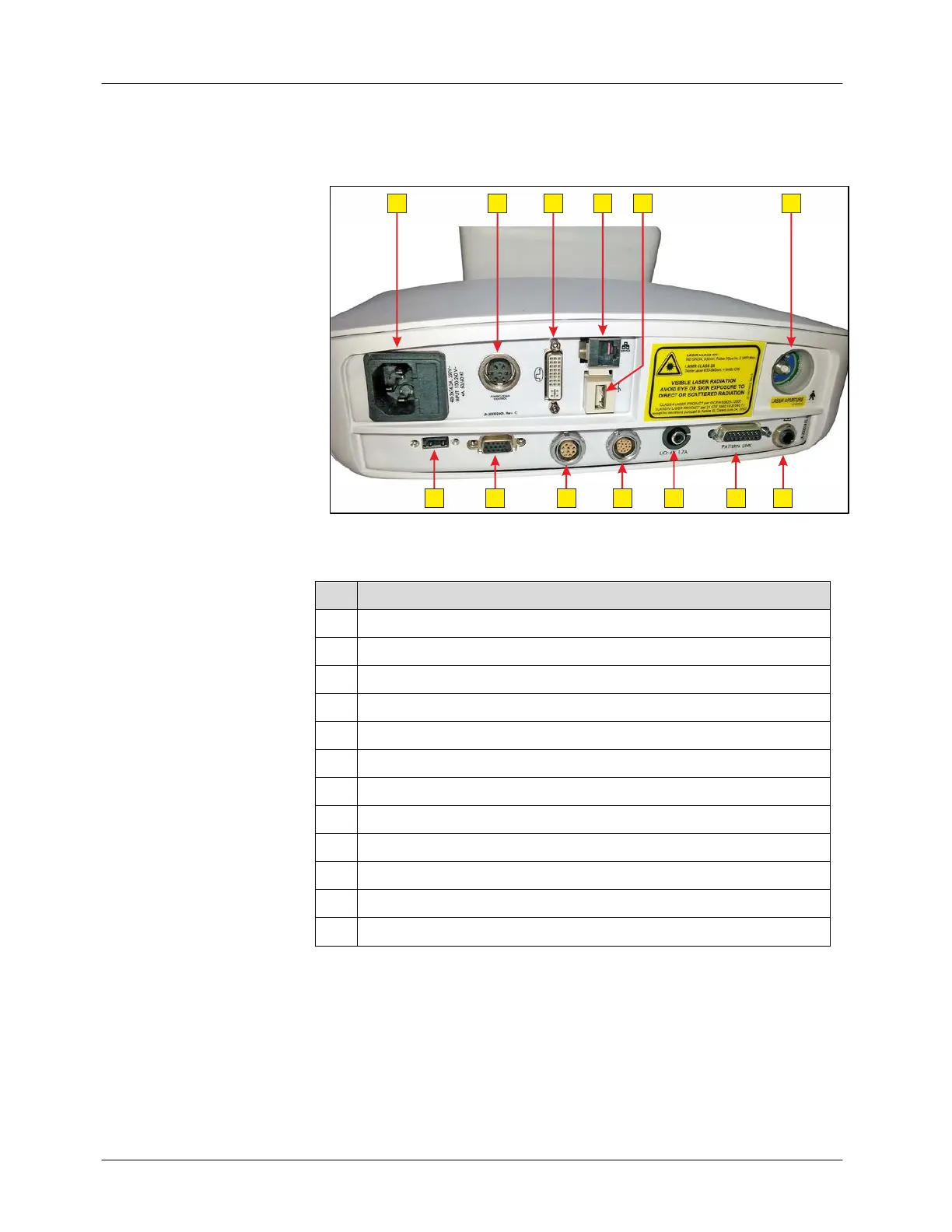
The rear panel of the Smart532 laser system is shown in Figure 4-3:
Figure 4-3: Smart532 Laser System – Rear Panel
# Description
1 Power cable connection port and fuse housing
2 Array connection port to aiming beam
3 DVI connection port
4 Ethernet connection port
5 USB connection ports
6 Fiber connection port (FC)
7 Disabled
8 Footswitch connection port
9 Eye safety filter (ESF) connection port
10 LIO illumination connection port
11 Array data connection port
12 Remote interlock connection port