214658 33 Revision A
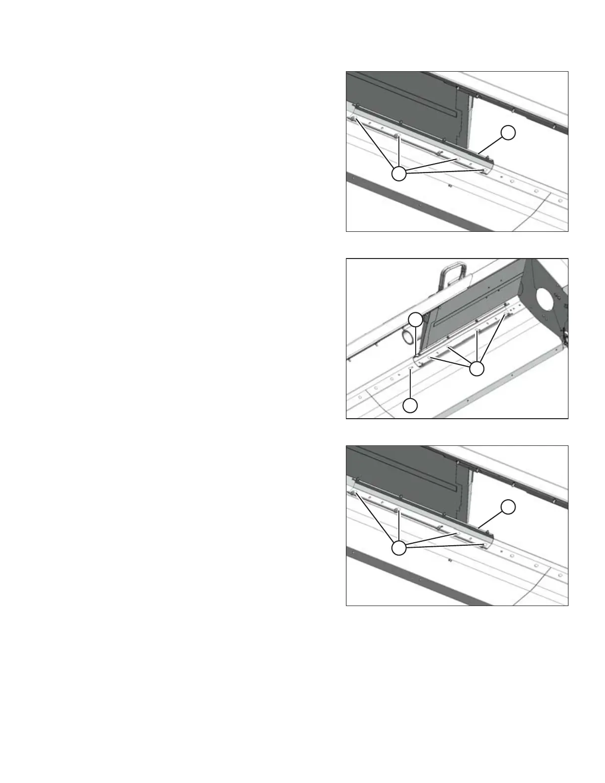
Figure 4.5: Right Stripper – Narrow Opening
6. Remove four bolts (A) attaching right stripper
assembly (B) to the frame.
Figure 4.6: Left Stripper – Wide Opening
7. Reinstall the four bolts (A) where the stripper
assembly (B) mounting holes line up with the frame.
Tighten bolts.
8. Install M12 x 30 carriage bolt (C) and nut (provided in
hardware bag) in the existing hole.
Figure 4.7: Right Stripper – Narrow Opening
9. Remove four bolts (A) attaching right stripper
assembly (B) to the frame.
RECONFIGURING HEADERS