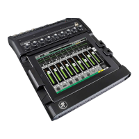
Mackie DL806 and DL1608 Reference Guide
131
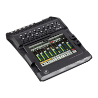
Gain Reduction Meter – The gain reduction meter displays the input channel gain reduction
from the gate and compressor. The single meter shows the sum of the total reduction applied
by the gate and compressor.
It illuminates from right to left and is 20 dB when fully lit.
To learn more about dynamics, check out chapter 10 starting on page 68.
Channel Faders and Input Meters – The touch sensitive faders adjust the level of each channel
goingtotheselectedoutput.Adjustmentsaremadebytouchinganddraggingchannelfaders
upanddown.Touchedchannelfaderswill“grow&glow”toindicatethattheyarebeingadjusted.
Thefaderlevelrangesfrom–∞to+10dBasindicatedbythescaleontheleft.
The input meters (next to each channel fader) display the input signal level to the channel before all
channelprocessing.ChangesmadetotheEQ,muteandfaderdonotaectthesemeters.Thismeter
should remain green with the occasional bump into the yellow zone. Turn down the gain knob if the
inputmeterremainsconsistentlyyellow.Iftheinputistoohigh[overloading],aclipindicatoratthe
topofthemeterwillilluminatered.Ifclippingoccurs,reducethegain.Unlinkedchannelsdisplay
mono meters, while linked channels display stereo meters. How to link channels is discussed on
page 133.
Red[clipping]=–3dBFS
Green to yellow = –18 dBFS
Green[bottom]=–90dBFS
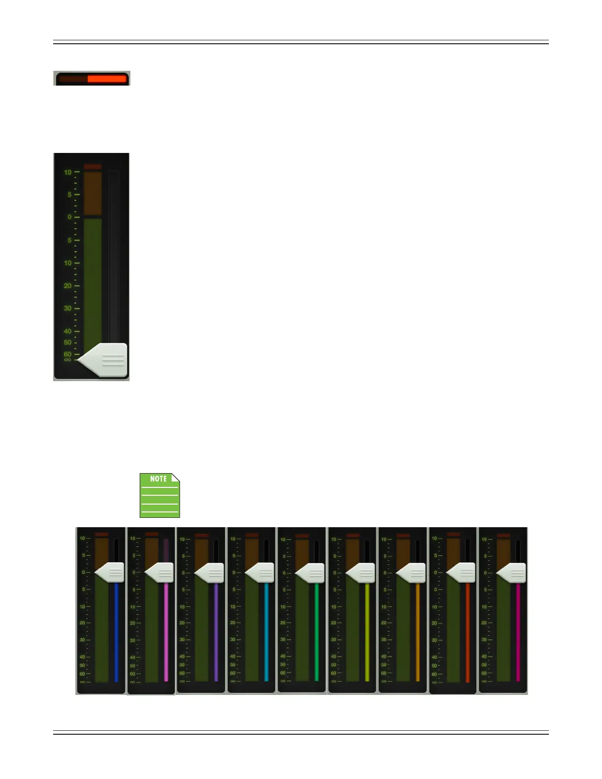
Selected Output Indicators – Directly to the right of each input meter (and underneath each fader
cap) are the selected output indicators. These vary by color for clear indication of which output type
is currently selected.
The output type is discussed in greater detail in the master fader section, starting on page 46.
There is no way you would ever see the image as shown below. It is just a point of
reference.Asmentionedabove,eachselectedoutputhasadierentcolorforclear
indication of which output type is currently selected. This is especially useful in the
mixer view.
LR AUX 1 AUX 2 AUX 3 AUX 4 AUX 5 AUX 6 REV DLY
 Loading...