OPERATING CONTROLS AND PROCEDURES RT9150E OPERATOR MANUAL
3-134
Published 2-23-2017, Control # 644-00
Telescope System Overview
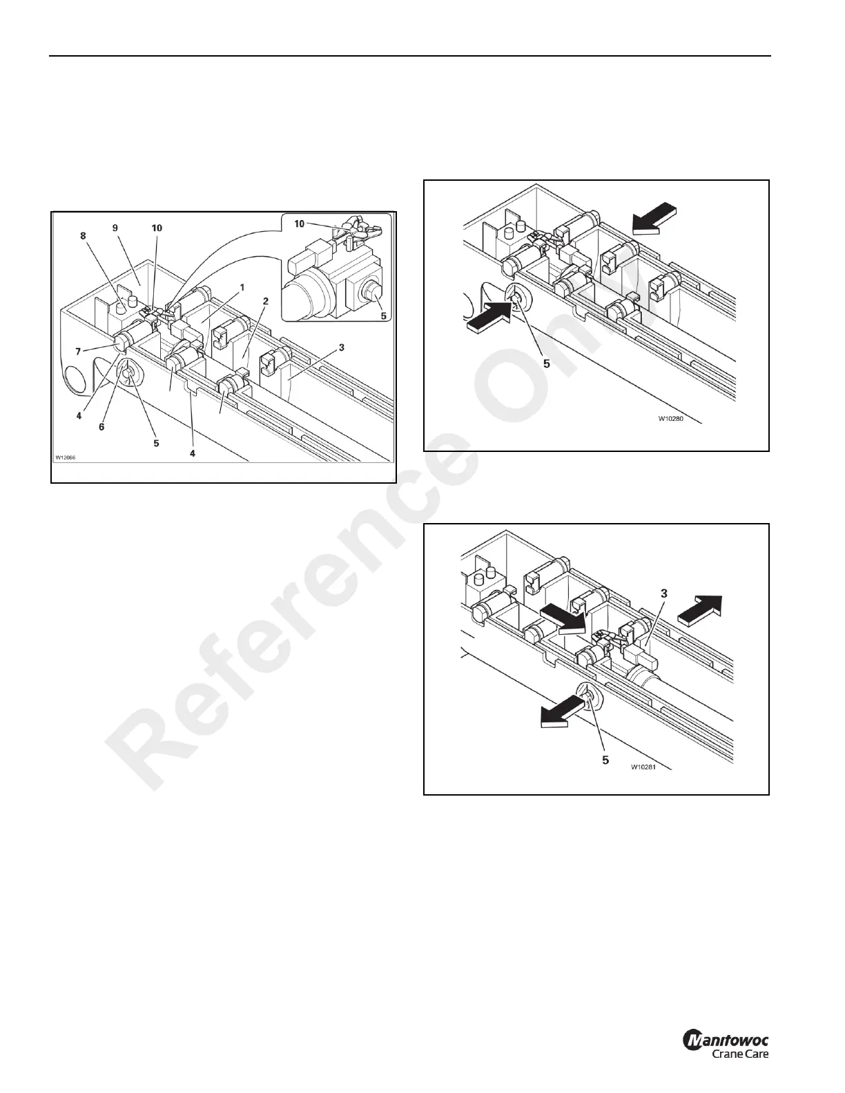
Refer to Figure 3-135.
The illustration shows the main boom assembly with the
telescope cylinder completely retracted into the main boom
base section (9) and the first three telescopic sections 1 to 3
(1) to (3).
Each telescopic section is equipped with two section locking
pins (7) which are extended by spring force and retracted by
the butterfly levers (10).
A telescopic section is locked when the locking pins (7) in
that section engage the cutouts (4) in the previous section.
The telescope cylinder piston rod (8) is attached to the boom
base (9). When hydraulic pressure is applied to the cylinder
the rod remains stationary and the cylinder extends.
The telescope cylinder has two locking pins (5) at the
bottom, which engage the section to be moved and the
butterfly mechanism at the top (10) to retract the section
locking pins.
After the telescope cylinder is positioned at a locking point:
• The cylinder locking pins (5) extend into the cutouts (6)
in the section to be moved, the telescope cylinder is now
locked.
• The butterfly mechanism (10) engages the section
locking pins (7) and retracts them, the telescopic section
is now unlocked.
• The cylinder can now be extended/retracted, moving the
section it is locked to.
For a more in-depth description of the telescoping process
refer to the next section.
Telescoping Process
The following section describes the normal operation of the
telescoping process from its initial starting point.
The telescoping processes consist of 4 steps:
1. Unlocking the telescoping cylinder (Figure 3-136);
a. The cylinder locking pins (5) retract, unlocking the
telescope cylinder.
2. Moving and locking the telescope cylinder
(Figure 3-137);
a. The telescope cylinder moves into the telescopic
section to be telescoped, e.g. section 3 (3).
b. The cylinder locking pins (5) extend, the telescope
cylinder is locked into section 3.
Reference Only