OPERATING CONTROLS AND PROCEDURES RT9150E OPERATOR MANUAL
3-152
Published 2-23-2017, Control # 644-00
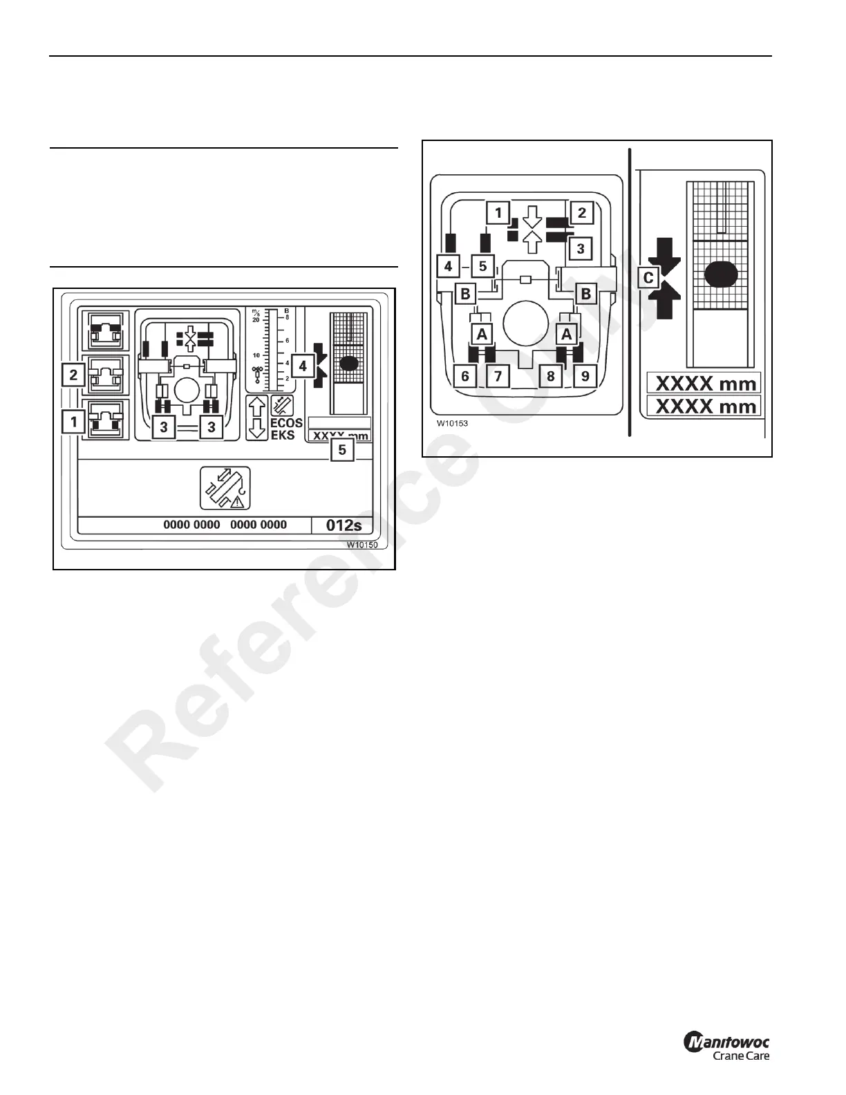
Extending and Locking the Telescope Cylinder
Refer to Figure 3-184.
You may not select Lock while the telescope cylinder is
retracting or extending. Under no circumstances should
you press the F3 button (1).
1. Slowly move the telescope cylinder into the next
extended telescopic section.
At the locking point:
- the arrows (4) are green,
- the display (5) shows the length for the current
locking point, refer to Tables for Approaching the
Locking Points, page 3-153.
2. Press the F3 button (1) once.
The telescope cylinder is locked. In Locked position:
- The locking pins (3) are green,
- the symbol (1) is grey,
- the symbol (2) is yellow.
3. You can now retract this telescopic section, refer to
Retracting and Locking A Telescopic Section, page 3-
150.
If There is an Error at a Proximity Switch
Refer to Figure 3-185.
Faulty proximity switches are shown in violet.
The displays (A), (B) and (C) only show the current positions
when all the corresponding proximity switches are free of
error.
Several proximity switches are related to the displays (A), (B)
and (C).
A: Proximity switches (6) to (9)
B: Proximity switches (4) and (5)
C: Proximity switches (1) to (3)
When a proximity switch is faulty (violet), then:
• The corresponding locking pins on the displays (A)
and (B) are always yellow.
• The corresponding arrows are not shown on the
display (C).
When an error occurs, you can determine the current
position more precisely based on the other, fault-free
proximity switches. The proximity switches show the
following positions:
• Display (C): Telescoping cylinder at the locking point
(1) At the locking point
(2) Behind the locking point
(3) In front of the locking point
• Display (B): Telescopic section locked
(4) Locked
(5) Unlocked
• Display (A): Telescoping cylinder locked
CAUTION
Equipment Hazard!
Selecting Lock during telescoping will cause the locking
pins on the telescopic section to slide out immediately and
damage or tear the electrical or hydraulic components in
the main boom.
Reference Only
 Loading...


