Chapter 8 Specifications
152
60、80、110、130、180 motor brake wiring:
Terminal
symbol
Terminal number
Terminal explanation
60/80 series
motors
110/130/180
series motors
DC+ 1 1
The brake power supply is DC,
without polarity insert requirement
DC- 2 2
PE —— 3
8.6.3
Encoder
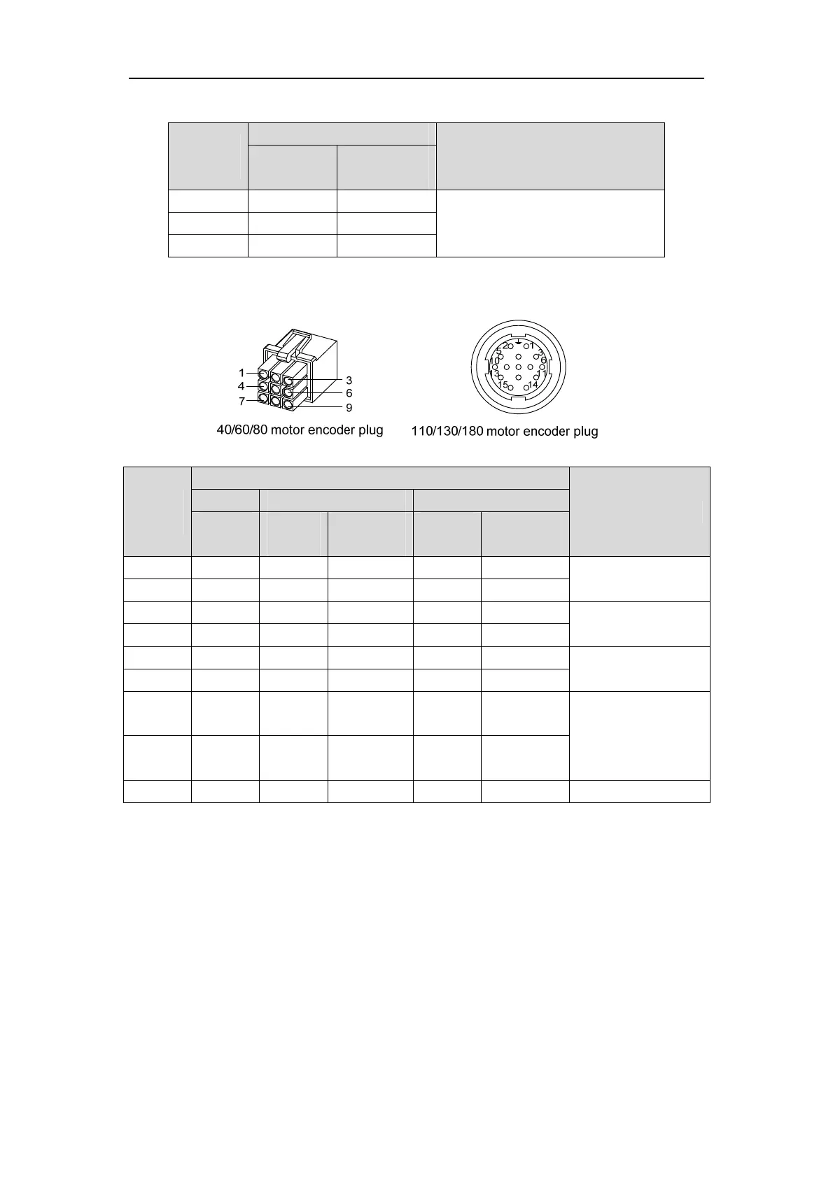
40、60、80、110、130、180 motor encoder wiring
Terminal
symbol
Terminal number
Terminal explanation
40motor 60/80motor 110/130/180motor
Absolute
type
Absolute
type
Incremental
type
Absolute
value
Incremental
type
SD+ 1 1 1 6 6
Encoder signal wire
SD- 2 2 2 7 7
MA+ 4 4 4 8 8
Clock output
MA- 5 5 5 9 9
VCC 6 6 6 2 2
Encoder
5V power input
GND 7 7 7 3 3
Battery+
☆
3 3 —— 4 ——
3.6Vbattery-powered
Battery -
☆
8 8 —— 5 ——
PE 9 9 9 1 1 Ground terminal
In this manual, “☆” means the typical functions of absolute encoder.“★” means the
typical functions of incremental encoder