Chapter 4 Running
50
4.4
Torque control mode
This part of the function needs to be improved.
4.5
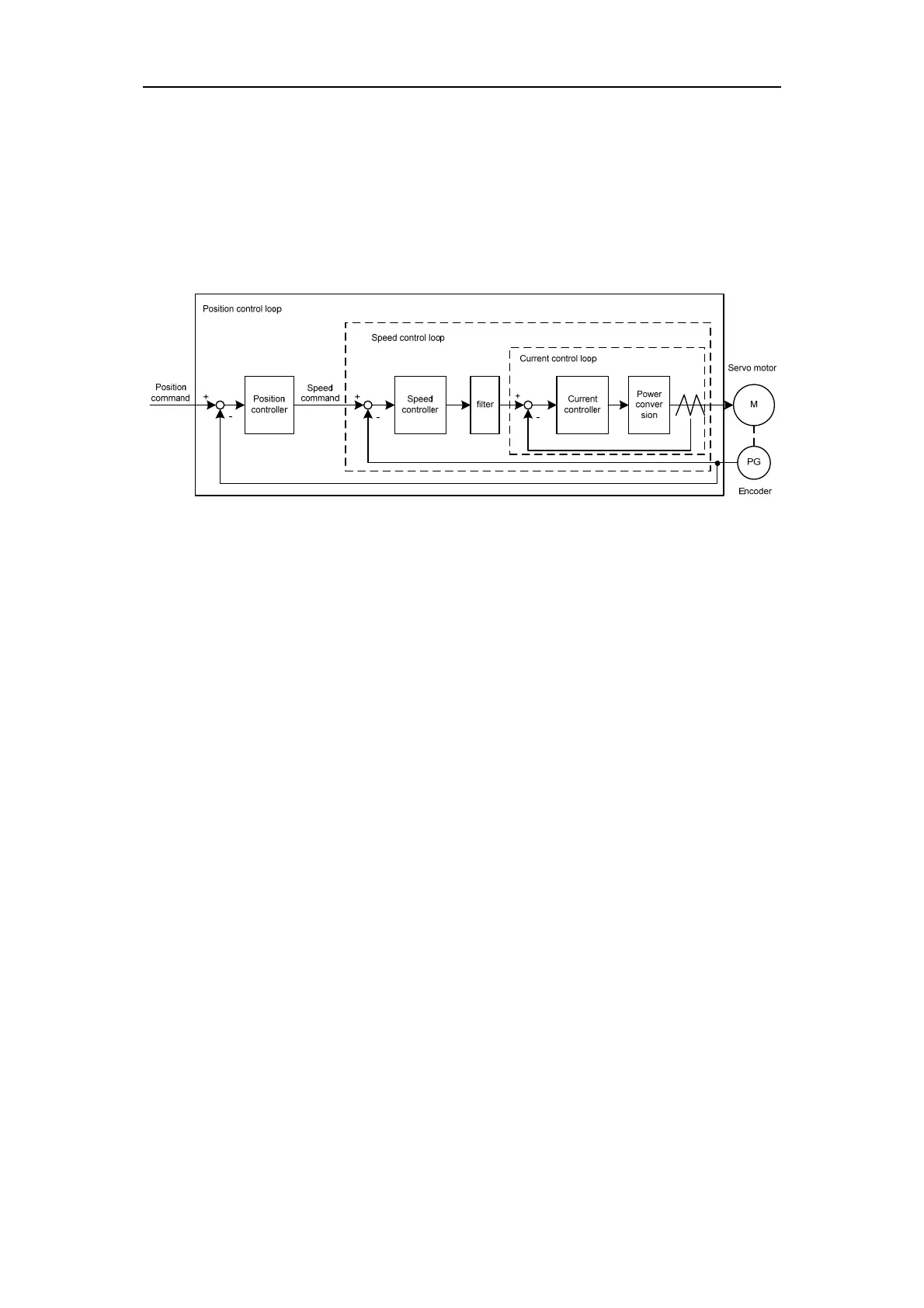
Gain adjustment
The driver includes three control loops: current control loop, speed control loop and
position control loop. The control block diagram is as follows:
In theory, the bandwidth of the control loop of the inner layer must be higher than that of
the outer layer, otherwise the whole control system will be unstable and cause vibration or
poor response. Therefore, the relationship between the bandwidth of the three control loops is
as follows:
Current loop bandwidth > speed loop bandwidth > position loop bandwidth
Since the driver has already adjusted the current control loop to the optimum condition,
the user only needs to adjust the speed control loop and position control loop parameters.