2.4 X1 control signal terminal
27
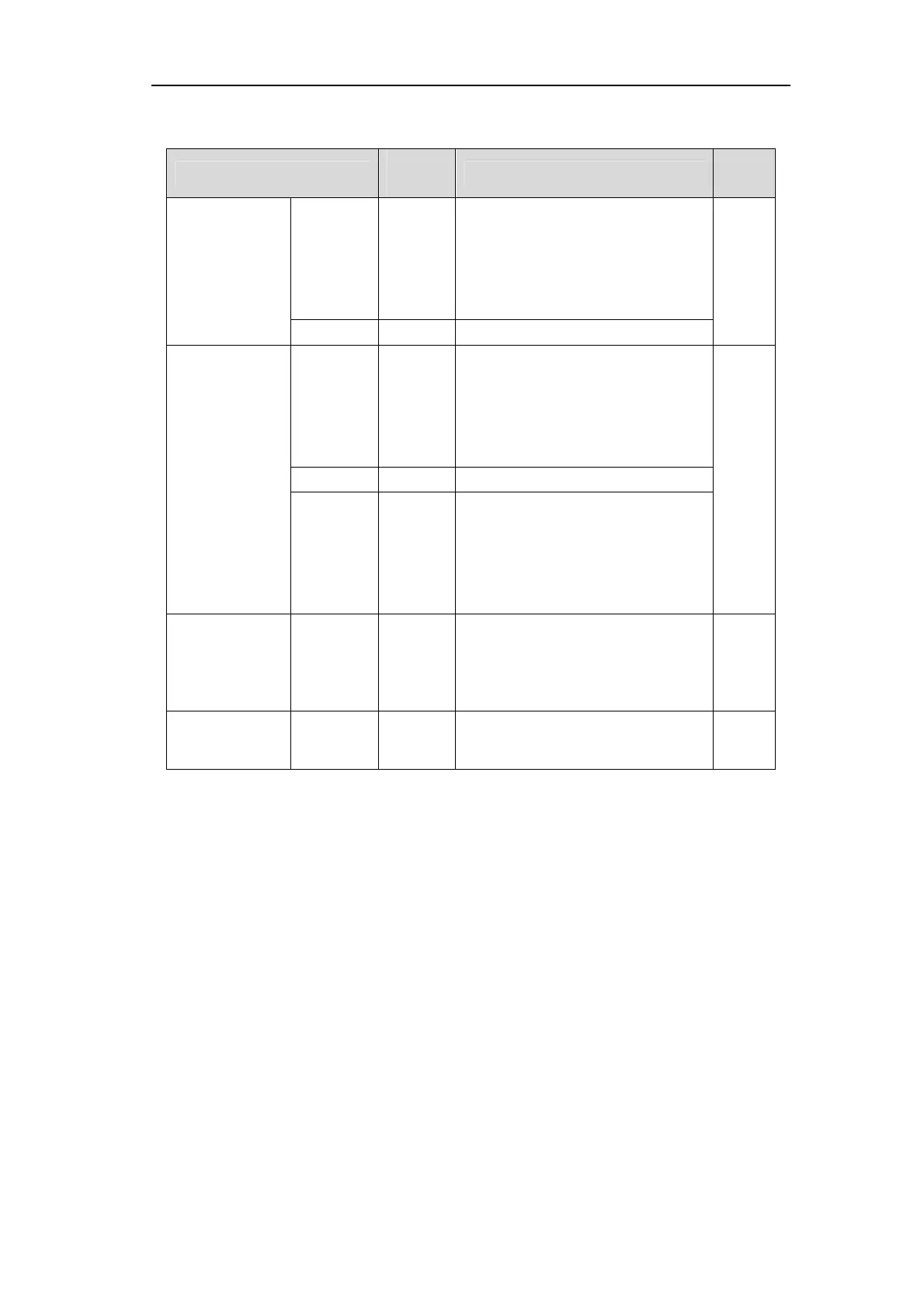
2.4.2
X1 terminal signal description
Signal name
Pin
number
Functions
Conne
ctor
Digital inputs
DI1
DI2
DI3
DI4
DI5
14
2
15
3
16
Photoelectric isolation input,
programmable function, defined by
parameters P100 ~ P104.
C1
COM+ 1 DI power supply (DC12V ~ 24V)
Digital outputs
DO1
DO2
DO3
4
17
5
Photoelectric isolation and output,
the maximum output capacity
50mA/25V, programmable function,
defined by the parameter
P130~P132.
C2
DOCOM 18 DO common terminal
DO4+
DO4-
DO5+
DO5-
11
23
12
24
Photoelectric isolation output,
maximum output capacity of
50mA/25V, programmable function,
digital difference output defined by
parameters
Position high
speed latch
HDI1+
HDI1-
HDI2+
HDI2-
20
7
19
6
High speed photoelectric isolation
input
C3
Shielding wire
protected area
Plug metal
housing
Connecting the shielded cable
shielded wire