Chapter 2 Wiring
28
2.4.3
X1 terminal interface type
The following will introduce the X1 interface circuit and the connection mode with the
upper control device.
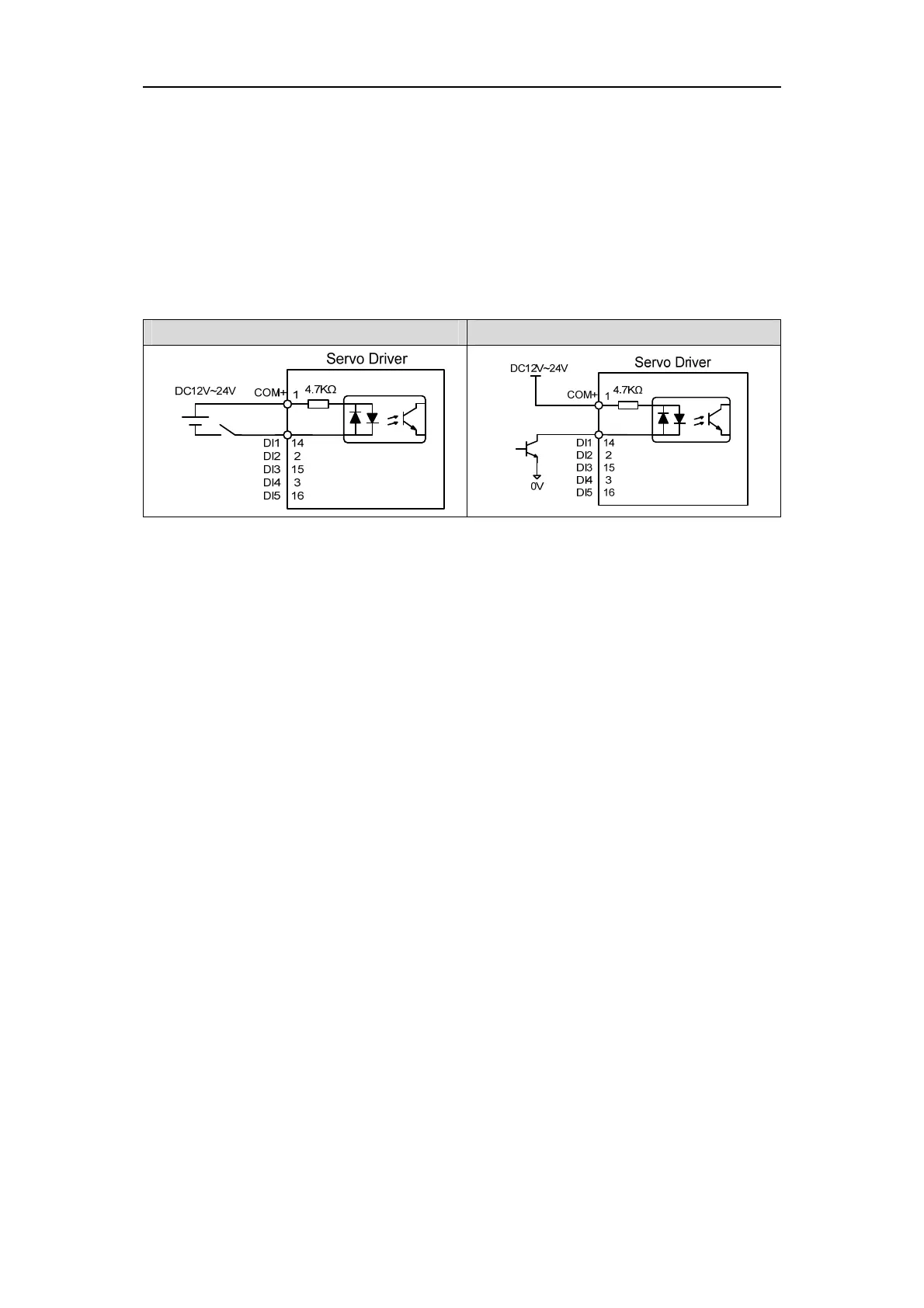
1. Digital input interfaces (C1)
For carrying on a control, the digital input interface circuit can be constructed by switch,
relay, open-collector triode, and photo-coupler and so on. To avoid contacting problem the relay
must be chosen with low current operation. External voltage is in the range of DC12V~24V.
C1-1:Switch input C1-2:Open collector triode
2. Digital output interfaces (C2)
The digital outputs use Darlington photo-coupler. It can be connected with relay,
photo-coupler. Matters of note are:
Inverting the polarity of DC power source, which is provided by the user, can cause the
servo driver damage.
The maximum voltage of external DC power supply is 25V, the maximum output current
is 50mA, and the total current for three channels is not in excess of 100mA.
When using relay like inductive loads, a free-wheel diode must be connected with the
inductive load in parallel. If the diode connects in wrong direction can cause damage to
the output circuit.
Owing to the low level of output is approximately 1V and cannot satisfy the TTL
low-level request, therefore cannot directly connect with the TTL circuit.