2.1 System construction and wiring
19
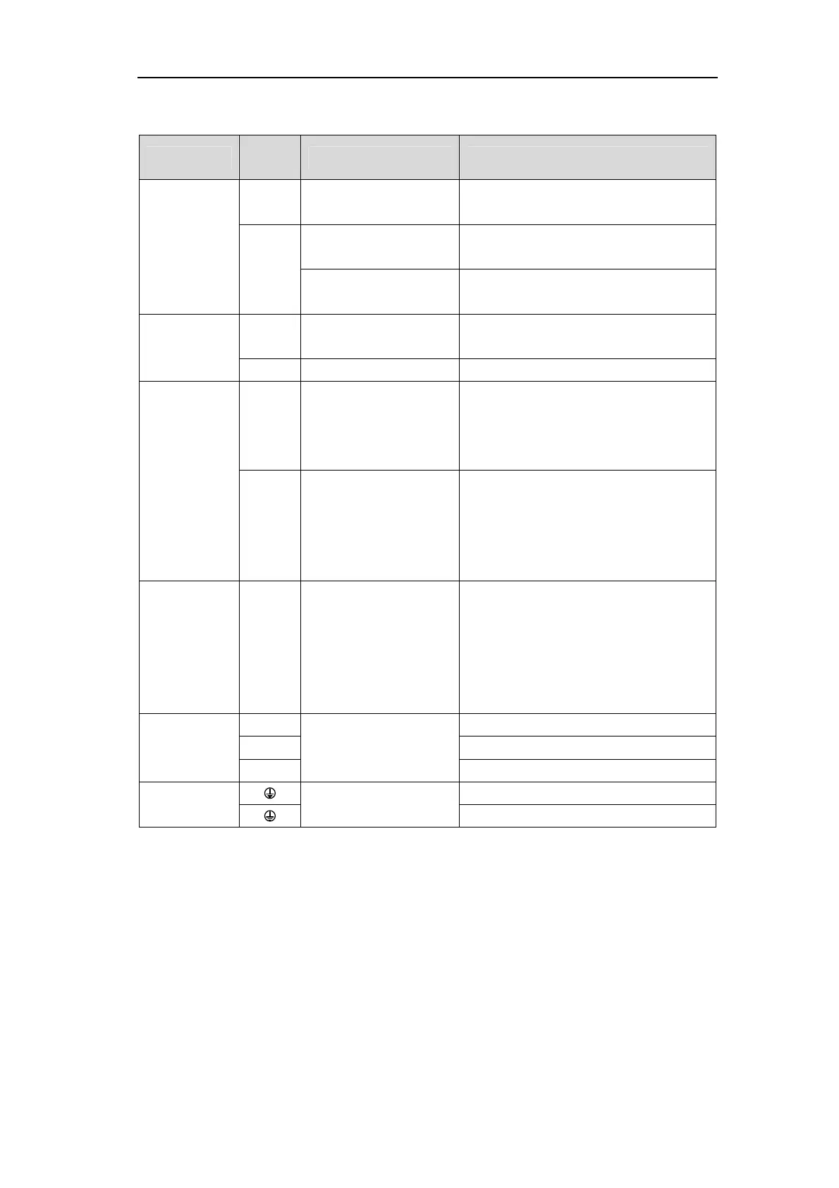
2.1.4
Strong terminal specification
Name
Terminal
symbol
model Detailed instructions
Main circuit
power input
terminal
L1
L2
GL1A0、GL1A8、GL3A0
Single-phase 220VAC
- 15% ~ + 10% 50/60 Hz
L1
L2
L3
GL5A5、GL7A5、GL120、
GL160、GL190、GL240
Three-phase 220VAC
-15%~+10% 50/60Hz
GH series
Three-phase 380VAC
- 15% ~ + 10% 50/60 Hz
Control circuit
power terminal
L1C
L2C
GL series
Single-phase 220VAC
- 15% ~ + 10% 50/60 Hz
24V、0V
GH series External DC24V
Brake resistance
terminal
P
B1
B2
GL1A0[Note1]、GL1A8、
GL3A0、GL5A5、GL7A5、
GL120、GL160、GH2A0、
GH3A5、GH5A4
When external brake resistance is needed,
disconnect B1、B2[Note 2], and the external
brake resistance is bonded to P、B1, so that B2
is suspended.
NC
P
B
GL190、GL240[Note1]
GH8A5、GH130、GH170
GH210、GH260、GH320
GH390
When using external braking resistor, must
first be open between P and B in braking
resistance line, at the same time the two
braking resistor inside thread on NC, then the
external braking resistor jumper on the P、B.
Power higher
harmonic
suppression
with DC reactor
connection
terminals
N1
N2
GL190、GL240、GH series
Need for power to suppress high order
harmonic, the connection between the N1, and
N2 [Note 2] DC reactor.
Motor
connection
terminal
U
EP3E series
Output to motor U phase power supply
V Output to motor V phase power supply
W Output to the motor W phase power supply
Earth terminal
EP3E series
Grounding terminal of motor housing
Driver grounding terminal
Note 1. GL1A0, GL240, GH260, GH320, GH390 have no internal brake resistor: GL1A0 generally does not
need to connect the brake resistor; However, when GL240 needs to connect the external brake resistor,
the external brake resistor should be straddled at the P and B ends, and the NC is suspended; GH260,
GH320, GH390 braking resistor in P and B side directly.
Note 2. It is the default internal brake resistance connection when delivered: B1 and B2 are short-connected, N1
and N2 are short-connected.