Chapter 4 Running
60
4.11
Electromagnetic brake
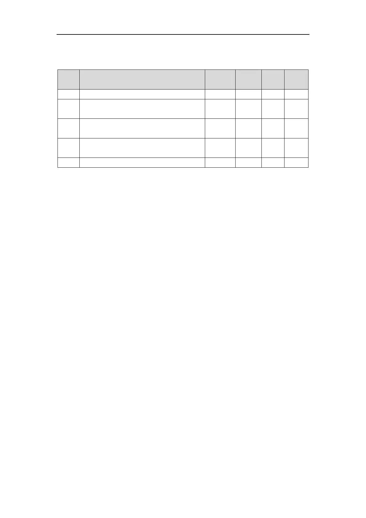
Electromagnetic brake related parameters:
Para
meter
Name Range
Default
value
Unit Usage
P165 Motor static speed detection point 0~1000 5 r/min ALL
P166
Motor static electromagnetic brake delay
time
0~2000 150 ms ALL
P167
Electromagnetic brake waiting time when the
motor is running
0~2000 500 ms ALL
P168
Speed of action of electromagnetic brake
when the motor is running
0~3000 100 r/min ALL
P169 Delay time of electromagnetic brake opening 0~1000 0 ms ALL
4.11.1
Electromagnetic brake use
The following figure is the wiring diagram of the brake. The brake release signal BRK of
the driver is connected to the relay coil, and the relay contacts are connected to the power
supply of the brake. The brake power supply is provided by the user and has sufficient
capacity. It is recommended to install surge absorbers to suppress surge voltage caused by
relay on/off operation. A diode can also be used as a surge absorber, which may cause a small
brake delay.
After the motor stops and is stationary (the speed is less than P165), the servo is OFF. At
this time, the motor continues to power on to maintain its position. After the brake is released
to brake, the power supply of the motor is removed after a period of stability (the time is
determined by parameter P166).
When the motor changes from the unenabled state to the enabled state, the delay time
between the motor current opening and the electromagnetic brake loosening (DO output
terminal BRK ON) is determined by parameter P169.
When the motor is running (the speed is greater than P165), the servo is OFF. At this time,
the motor current is cut OFF, and the brake continues to be released. After a period of delay,
the brake brakes. This is to make the motor slow down from the high speed rotation state to
low speed, and then make the mechanical brake action, to avoid damage to the brake. Delay
time is the time required for parameter P167 or motor speed to decelerate to the speed of
parameter P168. Take the minimum value of both.