Chapter 2 Wiring
26
2.4
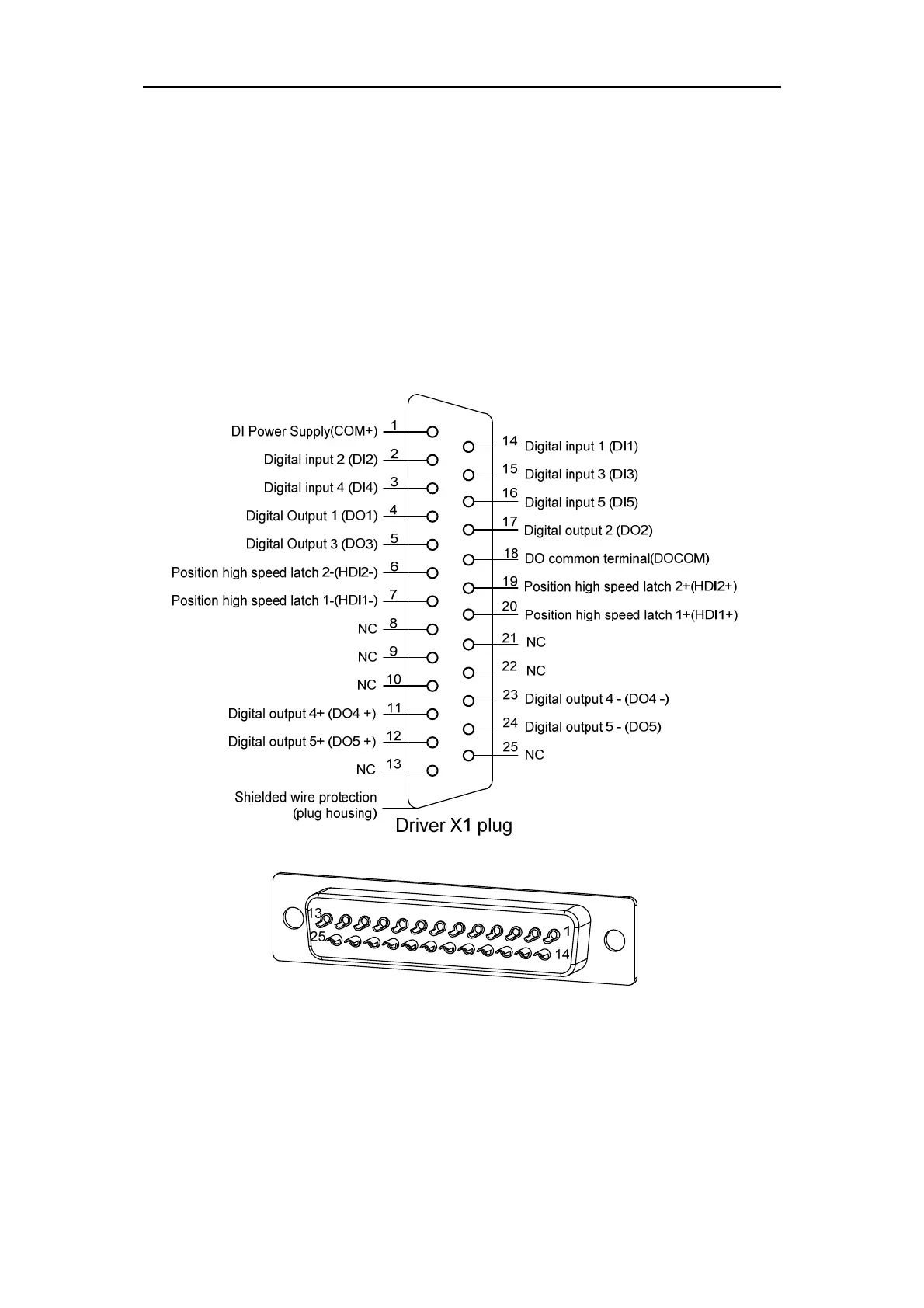
X1 control signal terminal
X1 control signal terminals for connected to the host controller signals, use DB25 socket,
signs include:
5 programmable inputs;
5 programmable outputs;
2 high-speed color code latch input.
2.4.1
X1 terminal plug
The X1 terminal plug adopts DB25 male head, and its shape and pin distribution are as
follows:
X1 plug welding pin distribution