GENERAL INFORMATION
00-00–4
HOW TO USE THIS MANUAL
id000000600900
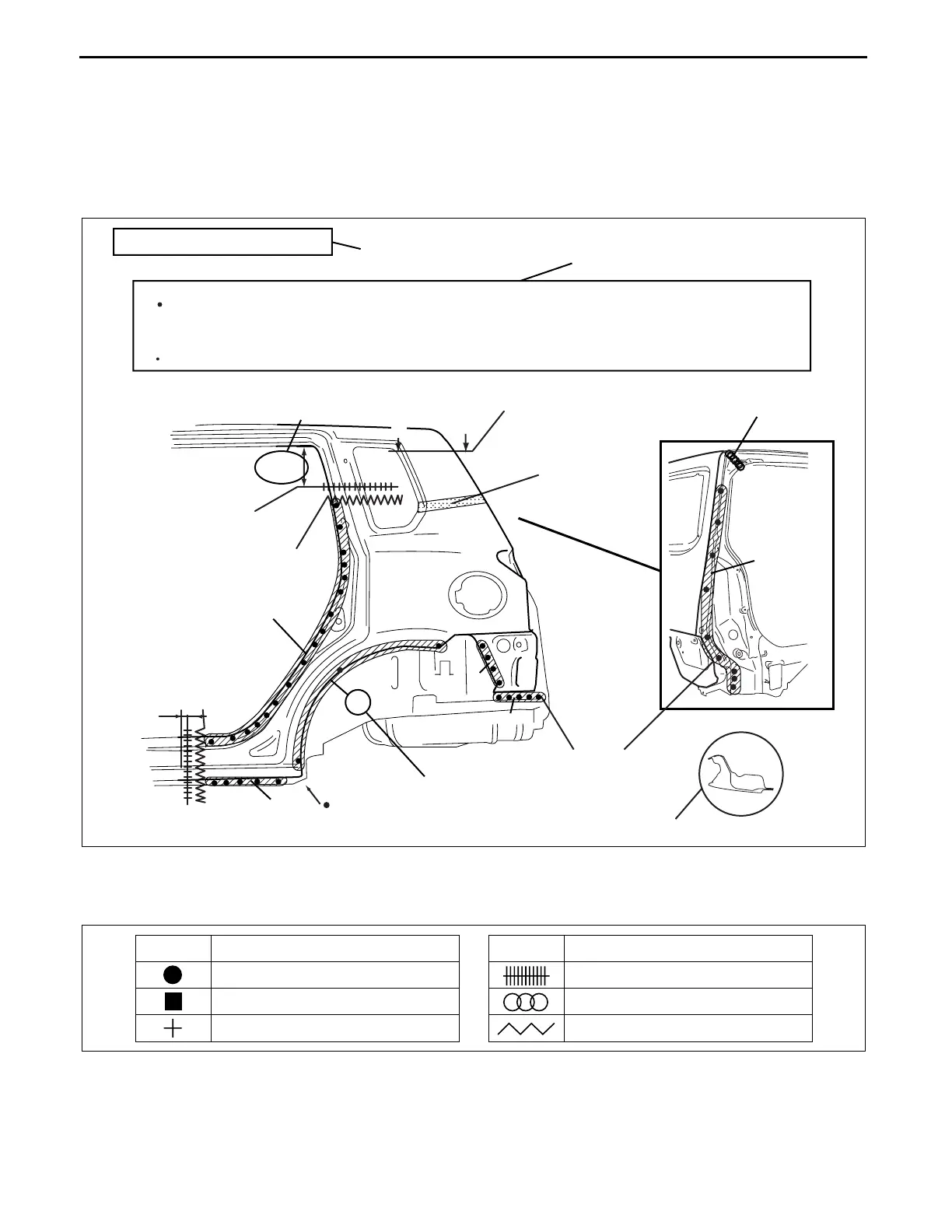
Efficient Replacement of Body Panels
• This section contains information on the body panels in regard to the welding types, number of spot welds, and
cut-and-join locations that are necessary for panel removal and installation.
• The type of weld and position are indicated by symbols.
• Some sections have notes concerning the operation being performed. Thoroughly read and understand the
notes before carrying out any procedures.
Example
Symbols of Panel Replacement
• The following 6 symbols are used to indicate the type of weld that is used when replacing body panels.
REAR FENDER PANEL REMOVAL
Shows operation section
Shows procedure, caution and note
BRAZE WELDING
Shows welding region
Shows a cross
Shows a insulator
Avoid cutting with a flame as the insulator (shaded) is flammable.
1.The rear fender panel and wheel house are joined with glue at the wheel arch line.
Drill the 17 weld locations indicated by (A), from the room side.
Caution
NOTE
CUT-AND-JOINT LOCATION
ROUGH CUT LOCATION
Shows a dimensions
{9.84in}
250mm
A-A
30mm
{1.18in}
Shows number of weld
Shows a cross location
A
A
(A)17
17
4
5
7
1
5
acxuub00000031
SYMBOL
MEANING
Spot welding
CO
2
arc welding (plug welding)
CO
2
spot welding
SYMBOL
MEANING
Continuous MIG welding (Cut-and-join location)
Braze welding
Rough cut location
acxuub00000032
3442-1U-09G.book 4 ページ 2009年7月22日 水曜日 午前11時7分