BODY STRUCTURE [PANEL REPLACEMENT]
09-80B–35
09-80B
FRONT SIDE FRAME (PARTIAL CUTTING) INSTALLATION [PANEL REPLACEMENT]
id098008742200
Symbol Mark
Installation Procedure
RH
Caution
x The cut-and-joint area indicates the maximum size range of the installation position.
1. Make a reinforcement panel using the material from the front side frame (inner).
2. To cut and join the new and existing parts, cut the new part at the specified location shown in the figure, and
chamfer the joint surfaces of the new and existing parts.
3. Drill holes for the plug welding before installing the new parts.
4. When installing the new parts, trial-fit new and existing parts, and then measure and adjust the body to conform
with standard dimensions.
5. Trial-fit the new and existing parts, weld the existing parts and the reinforcement, and then butt weld the new
and existing parts.
Caution
x Press fit the reinforcement panel and the body side material, and then weld them.
x To prevent weld bead drop from the reinforcement panel, weld the reinforcement plate such that
the weld bead are longer than their widths.
6. Install the front side frame (inner).
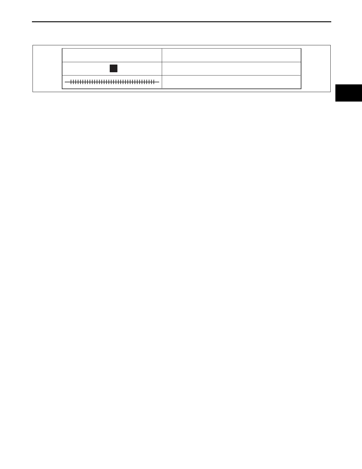
SYMBOL MARK
MEANING
PLUG WELDING (CO
2
ARC WELDING)
CONTINUOUS CO
2
ARC WELDING (CUT-AND-JOIN LOCATION)
am6xub0000004
7)$HOࡍࠫ㧞㧜㧜㧥ᐕ㧣㧞㧞ᣣޓ᳓ᦐᣣޓඦ೨㧝㧝ᤨ㧠㧟ಽ