Image Modes
10-7
4
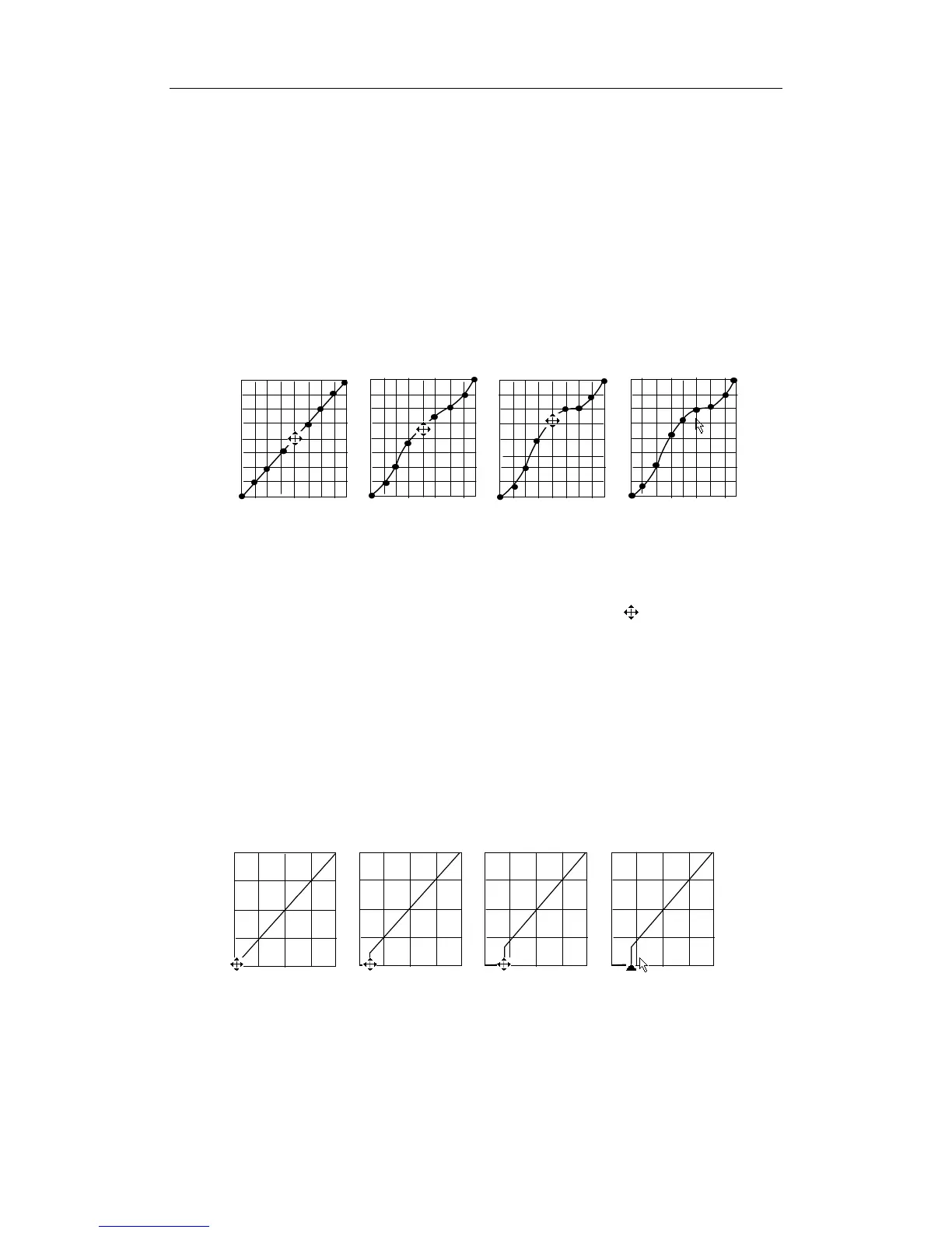
Press the [Set] key a second time to fix the node in the new position.
5
Repeat the above process to adjust multiple nodes.
6
Pressing the [Back] key will cancel the active adjustment, returning the node back to the
previous position.
7 Press the [Set] key on the [Linear] selection, and the gray map will transform to
become a 45° straight line.
8 Click [OK] to confirm the adjustment and exit the gray map toolbox.
9 Click [Cancel] to cancel all modification and resume the previous curve and exit the
gray map toolbox.
The adjustment is shown in the following figures:
Gray Rejection
The Gray Rejection feature processes and rejects gray scale levels within certain ranges.
1 Click the [Rejection] item in the B image menu or soft menu, and the Gray Rejection
toolbox will appear
.
2
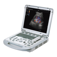
Move the cursor onto the ▲ marker. The cursor becomes a
. Press the [Set] key
and roll the trackball to move the ▲ marker along the horizontal axis.
You will notice
the B Mode image changes at the same time showing the modifications in real-time.
3
After the adjustment is complete, press the [Set] key a second time to fix the marker in
the new position.
4
Pressing the [Back] key will cancel the active adjustment, returning the node back to the
previous position.
5 Click [OK] to confirm the adjustment and exit the gray map toolbox.
6 Click [Cancel] to cancel all modification and resume the previous curve and exit the
gray map toolbox.
The adjustment is shown in the following figures:
γ Correction
z
The γ correction is used to correct non-linear distortion of images.
z The γ correction selections are represented by 0, 1, 2, and 3, respectively
representing coefficients of 1, 1.1, 1.2, and 1.3.