2. Product presentation
MiR600 User Guide (en) 08/2021 - v.1.0 ©Copyright 2021: Mobile Industrial Robots A/S. 22
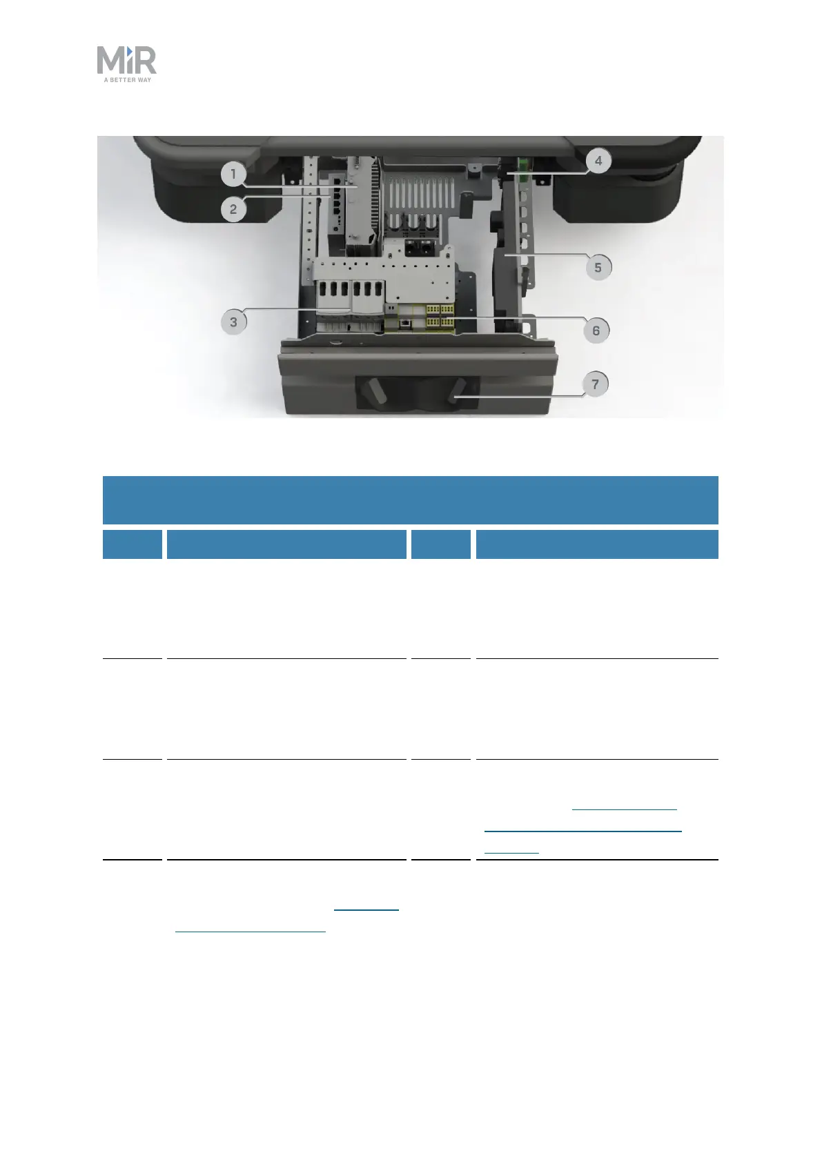
Figure 2.6. Internal parts of the front compartment.
Pos. Description Pos. Description
1 Robot computer: processes data
from the sensors and controls
the robot's navigation
2 Switch: enables communication
between the robot computer,
safety PLC, top interface, and
power board
3 Safe Torque Off contactors: cut
power to the robot's motors
when the robot enters Protective
or Emergency stop
4 GPIOmodule:manages signals
from the GPIOtop module
interface
5 Power board: controls the power
distribution for the motor
controller, robot computer, and
safety PLC
6 Safety PLC:controls the safety
system—see Safety-related
functions and interfaces on
page96
7 3D cameras: detect obstacles in
front of the robot—see Obstacle
detection on page84
Table 2.3.
Identification of internal parts in Figure 2.6