18. Interface specifications
MiR600 User Guide (en) 08/2021 - v.1.0 ©Copyright 2021: Mobile Industrial Robots A/S. 223
The GPIO supports low current/power devices like relays, contactors, lamps, and separate
PLC units.
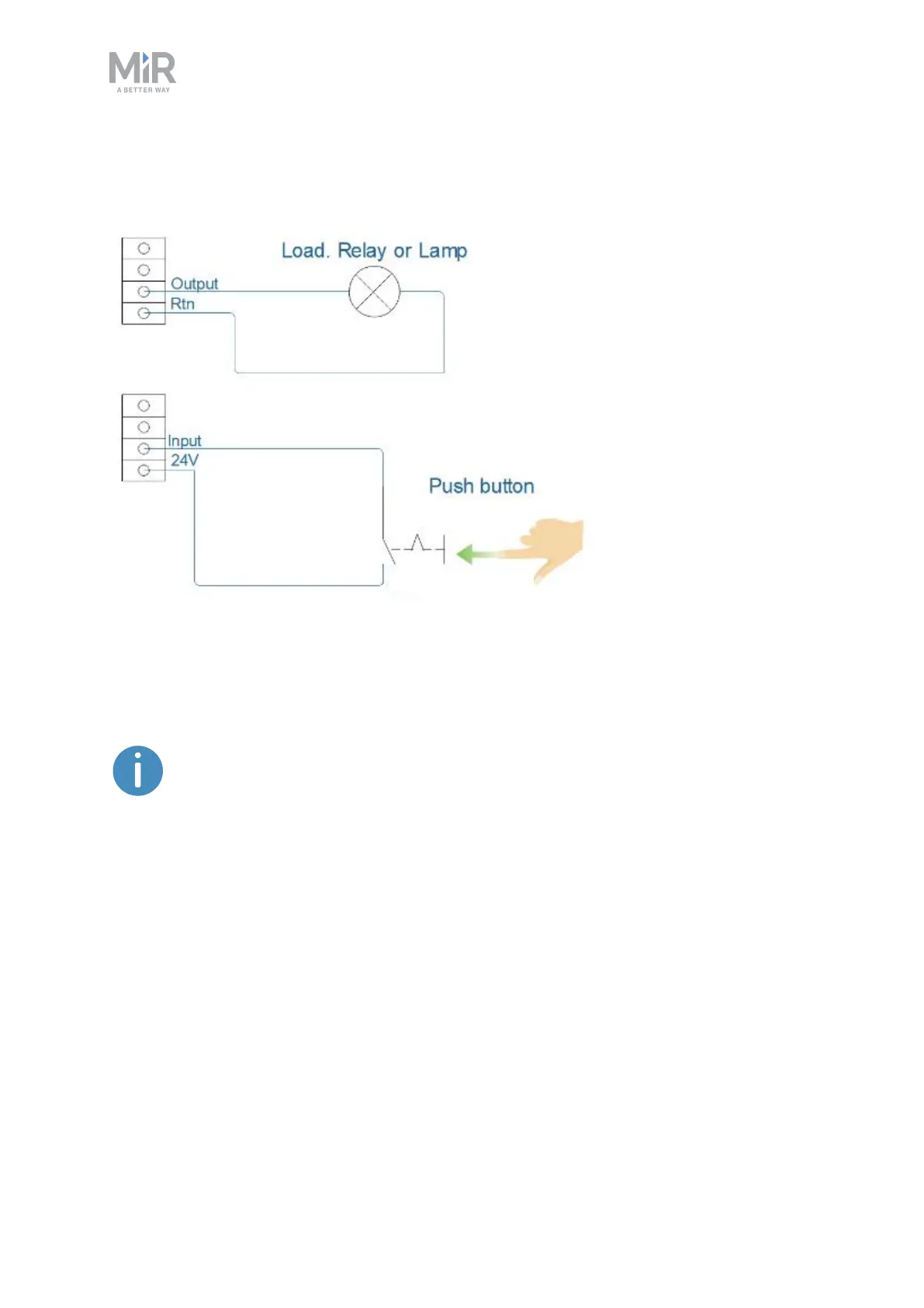
Figure 18.3. Outputs and RTNs are used to send signals to the top module, and inputs and 24V pins are used to
receive signals from the top module.
To use the GPIO for a top module of your own design, ensure that the Pallet
lift and Shelf features are disabled under System >Settings >Features. This
enables the GPIO interface to work as input and output to top modules that
can be controlled in missions. The pallet lift and shelf features use a different
kind of communication that is specific to the MiR top modules.
Outputs (O0, O1, O2, O3) can be toggled on and off by the robot in a Set I/Omodule mission
action or manually in Setup >I/O modules.
A top module can be connected to the output pins and monitor when they are active at 24V.
RTN is used as ground.
Inputs (I0, I1, I2, I3) can be used by the top application to send inputs to the robot. When 24V
is connected to the input pin, the robot registers the input as active.