18. Interface specifications
MiR600 User Guide (en) 08/2021 - v.1.0 ©Copyright 2021: Mobile Industrial Robots A/S. 224
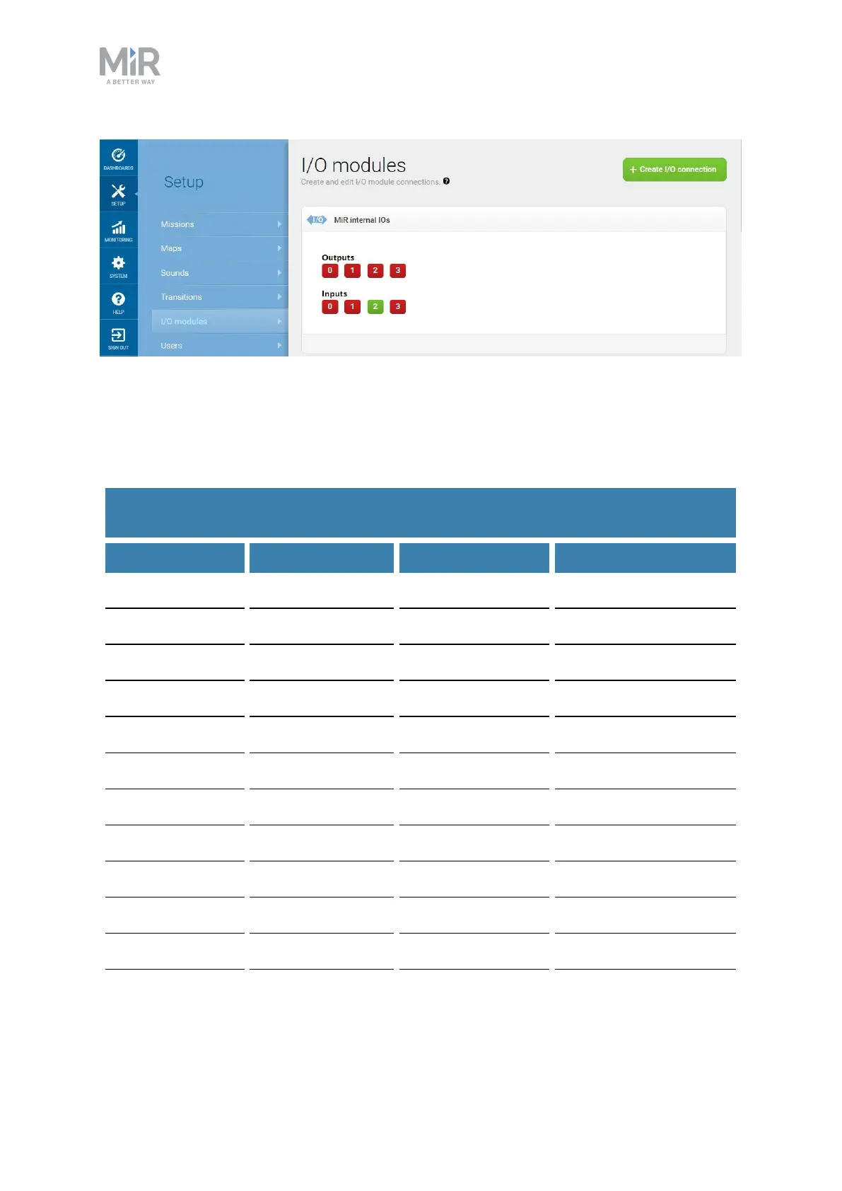
Figure 18.4. Example of I2 registered as high by the robot.
Output pins must be connected to RTN pins, and input pins must be connected to 24V pins.
Table 18.2 contains the description of the pins of the GPIO interface.
Pin number Signal name Max. current Description
1 O0 1A at 24 V Output 0
2 RTN Protected return
3 O1 1A at 24 V Output 1
4 RTN Protected return
5 O2 1A at 24 V Output 2
6 RTN Protected return
7 O3 1A at 24 V Output 3
8 RTN Protected return
9 I0 PNP Input 0
10 24V 1A at 24 V Protected output
11 I1 PNP Input 1
Table 18.2.
Description of the pins in the GPIOinterface
 Loading...


