103
Selection and protection of a motor
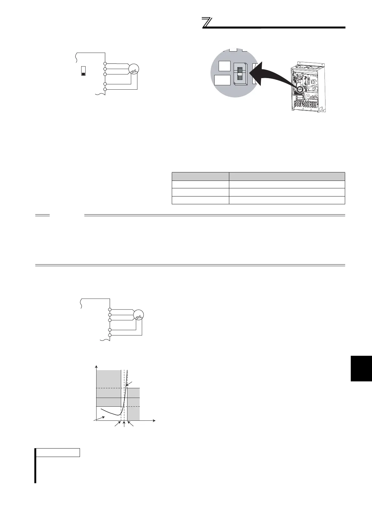
(6) PTC thermistor input using terminal AU (PTC signal)
Built-in PTC thermistor of the motor can be input to the PTC signal (AU terminal).
For the terminal used for PTC signal input, assign the function by setting "63" in Pr. 184 AU terminal function selection
and also set the AU/PTC switchover switch to the PTC terminal function. (The initial setting is the AU terminal
function.)
If a motor overheat state is detected for more than 10s according to the input from the PTC thermistor, the inverter
shuts off the output and outputs the PTC thermal fault signal (E.PTC).
(7) PTC thermistor input using terminal 2 (Pr. 561)
PTC thermistor input connection example
The input specifications of the PTC thermistor
are shown on the right.
Motor Temperature PTC Thermistor Resistance Value ()
Normal 0 to 500
Boundary 500 to 4k
Overheat 4k or higher
CAUTION
When the PTC signal was not assigned to Pr. 184 and the AU/PTC switchover switch was set to the PTC terminal function, the
function assigned to the AU terminal is always OFF. Reversely, when the PTC signal was assigned to Pr. 184 and the AU/PTC
switchover switch was set to the AU terminal function, a PTC thermal error (E.PTC) occurs since the function is always in a
motor overheat state.
When you want to input a current, assign the AU signal to the other signal.
Changing the terminal assignment using Pr. 178 to Pr. 189 (input terminal function selection) may affect the other functions. Set
parameters after confirming the function of each terminal.
PTC thermistor input connection
• Terminal 2 and terminal 10 are available for inputting of
motor built-in PTC thermistor output. When the PTC
thermistor input reaches to the resistance value set in
Pr. 561 PTC thermistor protection level, inverter outputs PTC
thermistor operation error signal (E.PTC) and trips.
To use terminal 2 as a PTC thermistor input, set voltage/
current input switch of terminal 2 to OFF (initial setting),
and set the input specification of terminal 2 to 0 to 5V
input (Pr. 73 Analog input selection = "1 (initial value), 3, 5,
11, 13, or 15" ).
• Check the characteristics of the using PTC thermistor,
and set the resistance value within a protection providing
temperature TN, just around the center of R1 and R2 in a
left figure. If the Pr. 561 setting is closer to R1 or R2, the
working temperature of protection goes higher (protection
works later), or lower (protection works earlier).
• PTC thermistor resistance can be displayed in operation
panel (FR-DU07), parameter unit (FR-PU07), or RS-485
communication when PTC thermistor protection is active
(Pr. 561 "9999").
PTC thermistor characteristics
REMARKS
• When using terminal 2 as PTC thermistor input (Pr. 561 "9999"), terminal 2 is not available for analog frequency command. Also
unavailable when using terminal 2 for PID control. Input the set point using Pr.133 or via communications.
• For the power supply terminal of PTC thermistor input, do not use a power supply other than terminal 10 (external power supply, etc).
Otherwise the PTC thermistor will not work properly.
Inverter
U
AU
PTC
V
W
AU(PTC)
Motor
SD
Inverter
AU/PTC switchover switch
Factory-set to "AU".
Set to the "PTC" position to
validate the PTC signal input.
Inverter
U
V
W
10
2
Moto
R2
R1
Pr. 561
TN
TN+ΔTTN-ΔT
Thermistor
temperature
TN: Rated operational temperature
Thermistor
resistance
Thermistor curve
Temperature-resistance
existing range
 Loading...


