104
Selection and protection of a motor
When using terminal 2 as a PTC thermistor input, the input PTC thermistor resistance can be displayed. To display the
PTC thermistor resistance, set "64" in Pr. 52 DU/PU main display data selection, Pr. 774 PU/DU monitor selection 1, Pr. 775
PU/DU monitor selection 2, or Pr. 776 PU/DU monitor selection 3. (Refer to page 136 and 318.)
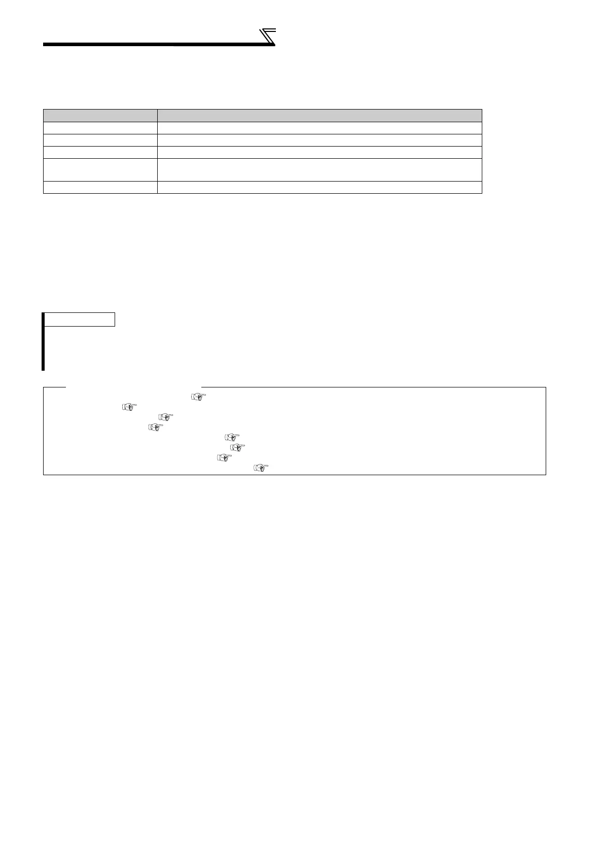
To monitor the PTC thermistor resistance via communication options, set as follows.
* For details, refer to the instruction manuals of each plug-in options.
(8) Terminal 10 calibration for PTC thermistor (Pr.986)
When using terminal 2 as PTC thermistor input, voltage calibration of terminal 10 is available.
• If the read value of Pr. 986 is a voltage data (Pr. 986 9999), the calibration is not necessary.
• If the read value of Pr. 986 is "9999", the calibration of terminal 10 is necessary. Measure the voltage between
terminal 10 and terminal 5 with a voltmeter, and set the voltage in Pr. 986.
• If the above calibration method is unavailable, short between terminal 10 and terminal 2, and set "8888" in Pr. 986.
Communication Option* Setting
FR-A7NC (CC-Link) Monitor code: H40
FR-A7NL (LonWorks) nviInvMonCode: H0040
FR-A7ND (DeviceNet) Class: 0x80, Instance: 1, Attribute: 74
FR-A7NP (Profibus)
PPO type support specification PNU: P1.64 (PNU number 1, Sub-Index number 64)
PPO type non-support specification IND: 0000H PNU: 3FH
FR-A7NF (FL remote) H1000020E
REMARKS
• When the combination of the main circuit board and control circuit has been changed, check the read value of Pr. 986. If the
read value is "9999", calibrate the terminal 10.
• Calibrate when the main circuit power is ON.
• Pr. 986 is not displayed in the initial value change list.
Parameters referred to
Pr. 52 DU/PU main display data selection Refer to page 136
Pr. 71 Applied motor Refer to page 105
Pr. 72 PWM frequency selection Refer to page 164
Pr. 73 Analog input selection Refer to page 166
Pr. 178 to Pr. 189 (Input terminal function selection) Refer to page 117
Pr. 190 to Pr. 196 (Output terminal function selection) Refer to page 123
Pr. 774 to Pr. 776 PU/DU monitor selection 1 to 3 Refer to page 318
Specifications of the terminal AU, terminal 2 and terminal 10 Refer to page 22

 Loading...


