EasyManuals Logo

Mitsubishi F700 Series User Manual

Mitsubishi F700 Series
408 pages
To Next Page IconTo Next Page
To Previous Page IconTo Previous Page
Page #122 background imageLoading...
Page #122 background image
111
Motor brake and stop operation
4
PARAMETERS
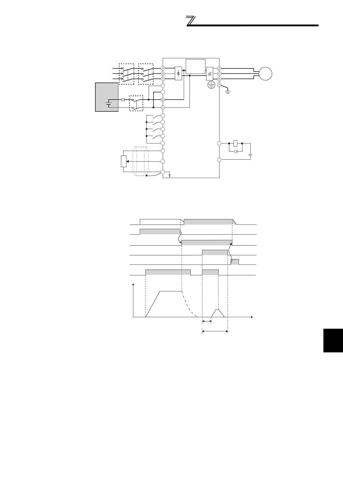
The following shows the connection diagram when switching to DC power supply using inverter power failure
detection.
*1 Assign the function using Pr. 178 to Pr. 189 (input terminal function selection).
*2 Assign the function using Pr. 190 to Pr. 196 (output terminal function selection).
Operation example 1 at power failure
DC power
R/L1
S/L2
T/L3
U
V
W
P/+
N/-
SE
Y85
IM
STF
STR
X70
X71
PC
R1/L11
S1/L21
Earth
(Ground)
10
2
2
3
1
5
(+)
(-)
*1
MC1
Three-phase AC
power supply
DC feeding permission signal
DC feeding cancel signal
Contact input common
Reverse rotation start
Forward rotation start
*1
*2
Inverter
Inrush
current
limit circuit
Frequency command
Frequency setting
potentiometer
1/2W1kΩ
24VDC
MCCB MC
DC feeding signal
MC1
Time
ON
ON
Back up operation
Motor
coasting
STF(STR)
DC power supplyAC power supply
ON
AC power supply
ON
Y85(MC)
ON
X70
ON
X71
Control power
supply
Output
frequency
(Hz)
Approx. 150ms

Table of Contents

Questions and Answers:

Question and Answer IconNeed help?

Do you have a question about the Mitsubishi F700 Series and is the answer not in the manual?

Mitsubishi F700 Series Specifications

General IconGeneral
Humidity95% RH or less (non-condensing)
Control MethodV/F control
Protection FeaturesOvercurrent, overvoltage, undervoltage, overheat, short circuit
Communication OptionsRS-485
Operating Temperature-10°C to +50°C
Storage Temperature-20°C to +65°C
AltitudeUp to 1000m above sea level
Overload Capacity150% for 60 seconds
Cooling MethodForced air cooling
Power Range0.75 to 630 kW (1 to 845 hp)
Output Voltage3-phase 200 to 240 VAC, 380 to 500 VAC (matching input voltage)

Related product manuals