112
Motor brake and stop operation
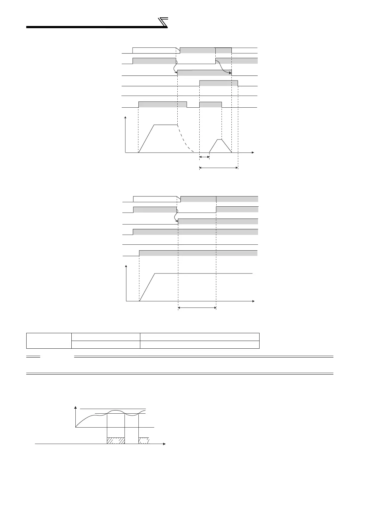
Operation example 2 at power failure (when DC power is restored)
Operation example 3 at power failure (when continuous operation is performed)
(7) Power supply specification at DC feeding
(8) Regenerative brake duty alarm output and alarm signal (RBP signal) (01800 or more)
400V class
Rated input DC voltage 537VDC to 679VDC
Permissible fluctuation 457VDC to 740VDC
CAUTION
As voltage between P/+ and N/- becomes 830VDC or more temporarily at regeneration, make selection of DC power supply
carefully.
100%: regenerative overvoltage protection operation value
[RB] appears on the operation panel and an alarm signal (RBP) is
output when 85% of the regenerative brake duty set in Pr. 70 is
reached. If the regenerative brake duty reaches 100% of the Pr.
70 setting, a regenerative overvoltage (E.OV1 to E.OV3) occurs.
The inverter does not shut off the output when the alarm signal is
output.
For the terminal used for the RBP signal output, assign the
function by setting "7" (positive logic) or "107" (negative logic) in
any of Pr. 190 to Pr. 196 (output terminal function selection).
Time
ON
ON
Back up operation
Motor
coasting
Output
frequency
(Hz)
STF(STR)
DCAC AC
Control power
supply
ON
Power restoration
AC power supply
ON
Y85(MC)
ON
OFF
X70
X71
Turns OFF after
stop while running
Approx. 150ms
Time
ON
Back up operation
Output
frequency
(Hz)
STF(STR)
DCAC
AC
Control power
supply
ON
Power restoration
AC power supply
ON
Y85(MC)
ON
OFF
X70
X71
Remains ON while running
Ratio of brake duty
to the Pr. 70 setting
Regenerative
brake prealarm
(RBP)
OFF
ON
100%
85%
Tim
ON

 Loading...


