237
Communication operation and setting
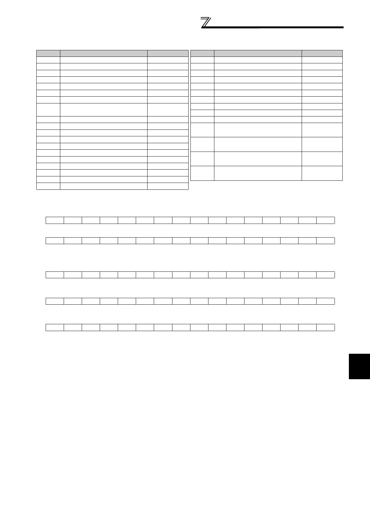
Real-time monitor
Refer to page 136 for details of the monitor description.
*1 The setting depends on capacities. (01160 or less/01800 or more)
*2 Input terminal monitor details (when the terminal is ON: 1, when the terminal is OFF: 0, : undetermined value)
*3 Output terminal monitor details (when the terminal is ON: 1, when the terminal is OFF: 0, : undetermined value)
*4 When Pr.37 = "1 to 9998" or Pr. 144 = "2 to 10, 102 to 110," the unit is an integral value (one increment). (Refer to page 134)
*5 Option input terminal 1 monitor details (input terminal status of FR-A7AX when the terminal is ON: 1, when the terminal is OFF: 0) -all terminals
are OFF when an option is not fitted
*6 Option input terminal 2 monitor details (input terminal status of FR-A7AX when the terminal is ON: 1, when the terminal is OFF: 0,
: undetermined value) -all terminals are OFF when an option is not fitted
*7 Option output terminal monitor details (output terminal status of FR-A7AY/A7AR when the terminal is ON: 1, when the terminal is OFF: 0,
: undetermined value) -all terminals are OFF when an option is not fitted
*8 The monitored values are retained even if an inverter fault occurs. Resetting will clear the retained values.
b15 b0
CS RES
STOP
MRS JOG RH RM RL RT AU STR STF
b15 b0
ABC2 ABC1
FU OL IPF SU RUN
b15 b0
X15 X14 X13 X12 X11 X10 X9 X8 X7 X6 X5 X4 X3 X2 X1 X0
b15 b0
DY
b15 b0
RA3RA2RA1Y6Y5Y4Y3Y2Y1Y0
Register Description Increments
40201 Output frequency/Speed
*4 *8
0.01Hz/1
40202 Output current
*8
0.01A/0.1A
*1
40203 Output voltage
*8
0.1V
40205
Frequency setting value/Speed
setting
*4
0.01Hz/1
40206 Running speed 1r/min
40208 Converter output voltage 0.1V
40209 Regenerative brake duty 0.1%
40210
Electronic thermal relay function
load factor
0.1%
40211 Output current peak value 0.01A
/0.1A
*1
40212 Converter output voltage peak value 0.1V
40213 Input power 0.01kW/0.1kW
*1
40214 Output power 0.01kW/0.1kW
*1
40215 Input terminal status
*2
40216 Output terminal status
*3
40217 Load meter
0.1%
40220 Cumulative energization time
1h
40223 Actual operation time
1h
40224 Motor load factor
0.1%
40225 Cumulative power 1kWh
40250 Power saving effect Variable
40251 Cumulative saving power Variable
40252 PID set point
0.1%
40253 PID measured value
0.1%
40254 PID deviation
0.1%
40258 Option input terminal status 1
*5
40259 Option input terminal status 2
*6
40260 Option output terminal status
*7
40264 PTC thermistor resistance 0.01k
40267 PID measured value 2 0.1%
40277
32-bit cumulative power
(lower 16-bit)
1kWh
40278
32-bit cumulative power
(upper 16-bit)
1kWh
40279
32-bit cumulative power
(lower 16-bit)
0.01kWh/
0.1kWh
*1
40280
32-bit cumulative power
(upper 16-bit)
0.01kWh/
0.1kWh
*1
Register Description Increments

 Loading...


